Exhaust gas purifying device

a technology of exhaust gas and purification device, which is applied in the direction of physical/chemical process catalyst, metal/metal-oxide/metal-hydroxide catalyst, separation process, etc., to achieve the effect of suppressing degradation, high temperature of exhaust gas supplied to the catalyst converter, and excelling heat resistan

Active Publication Date: 2011-06-02
HONDA MOTOR CO LTD
View PDF11 Cites 9 Cited by
  • Summary
  • Abstract
  • Description
  • Claims
  • Application Information

AI Technical Summary

Benefits of technology

Since high temperature exhaust gas is provided to the upstream catalyst in a state in which circling and diffusing thereof is suppressed by configuring in this way, it efficiently reaches over the entirety of the upstream catalyst, a result of which the upstream catalyst rapidly rises in temperature to cause the purification reaction to initiate.
According to the present invention, since a catalytic converter is provided immediately downstream of the exhaust manifold, the temperature of the exhaust gas supplied to the catalyst converter is high. After this high temperature exhaust gas is sufficiently rectified by a flow regulating path of a predetermined length, it flows into the neck portion. Herein, since the flow regulating path is configured to gradually narrow in width to the downstream side, the width of the neck portion pointed end provided in the flow regulating path is also narrow, and the radius of curvature R is small, whereby circling of the exhaust gas is suppressed.
In addition, the upstream catalyst and the downstream catalyst excel in heat resistance, and thus suppress degradation due to heat and also simultaneously purify NOx, NMOG, HC, CO, etc. Therefore, it is possible to maintain sufficient exhaust gas purification performance and reduce the amount of noble metal used.

Problems solved by technology

However, since time is required in the temperature rise of the second catalytic converter in the exhaust gas purifying device illustrated in Patent Document 1, there is no other choice but to ultimately increase the amount of noble metal used in order to shorten this time.

Method used


Image

  • Exhaust gas purifying device
  • Exhaust gas purifying device
  • Exhaust gas purifying device

Examples


examples

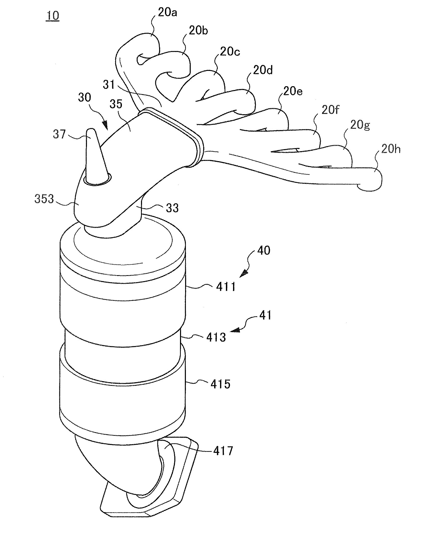
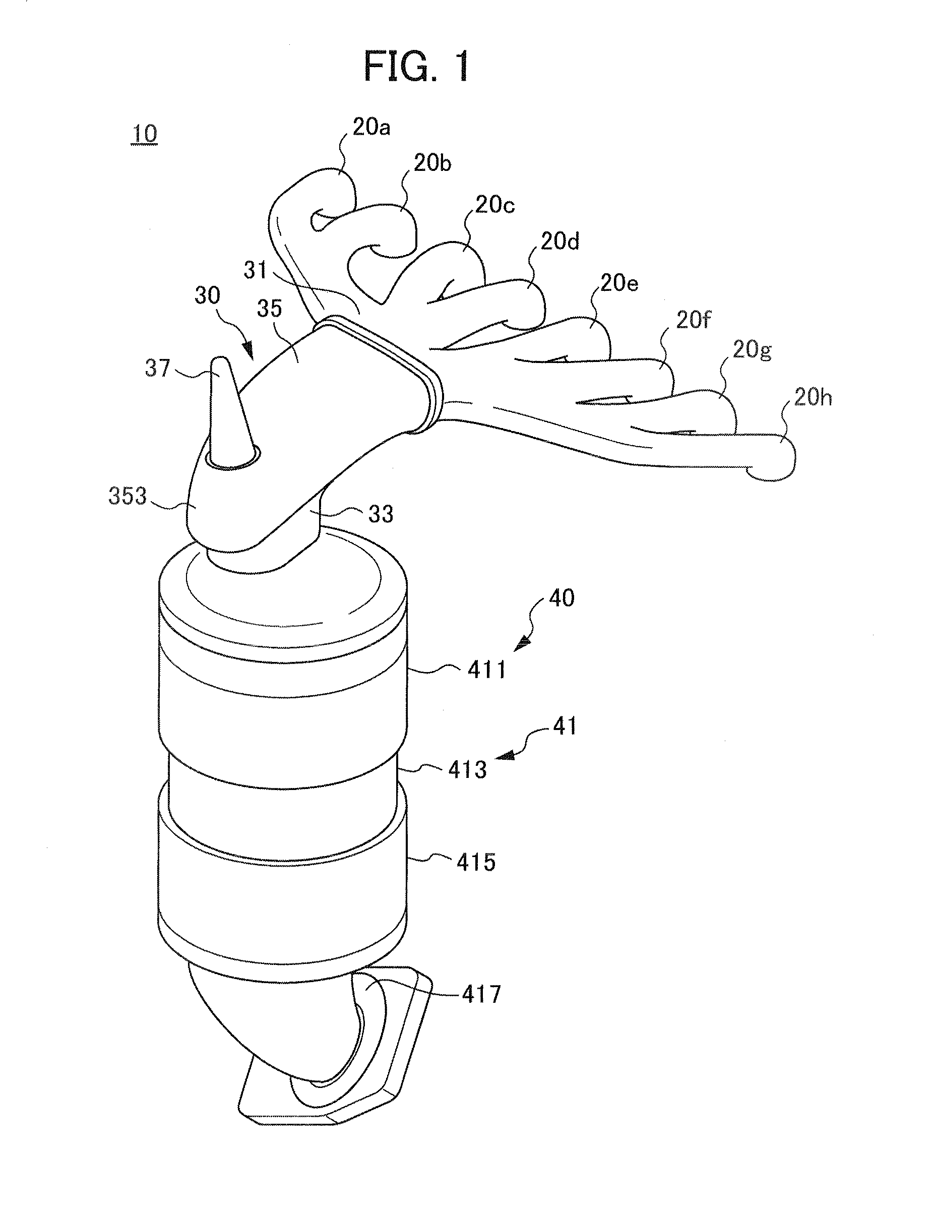
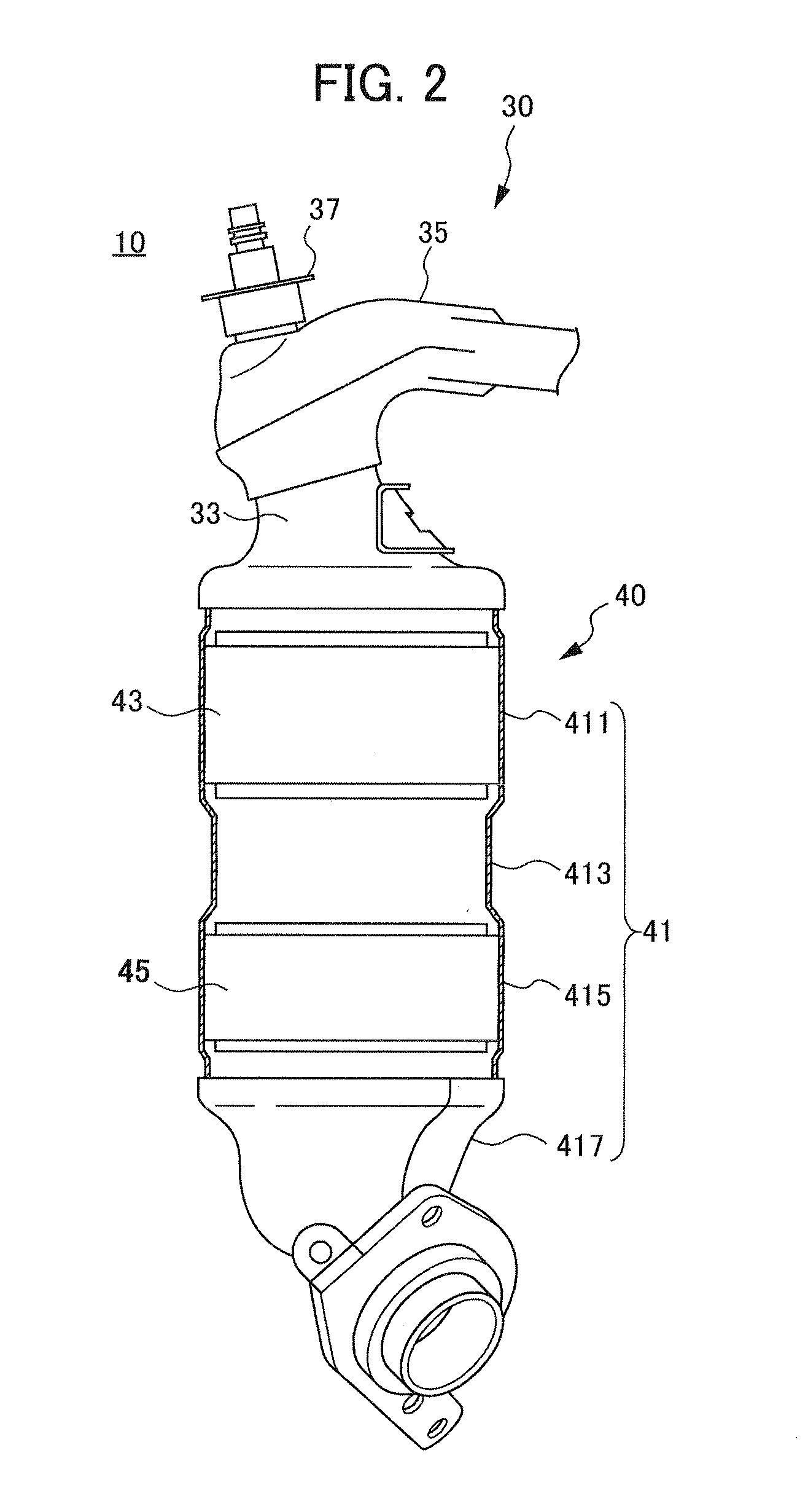
The following evaluation was performed by connecting, to the exhaust ports of a gasoline engine of 4-cylinder, 1800 cc displacement, the exhaust gas purifying device 10 (present invention) in which the flow regulating path 35 is 125 mm long and gradually narrows in width to the downstream side, and the radius of curvature of the end surface is 20 mm; an exhaust gas purifying device (conventional example 1, refer to FIG. 8) that differs from the exhaust gas purifying device 10 in the aspects of the flow regulating path 35 being 90 mm long, the width being substantially constant, and the radius of curvature of the end surface being 32.5 mm; and an exhaust gas purifying device (conventional example 2) that differs from the exhaust gas purifying device 10 in the aspects of being a structure (dual-Y structure) in which the runners 20a to 20d and runners 20e to 20e are merged separately, and these merged pipes (70 mm in length) further merge. It should be noted that the carrier used was a...


PUM

PropertyMeasurementUnit
widthaaaaaaaaaa
widthaaaaaaaaaa
widthaaaaaaaaaa

Abstract

An exhaust gas purifying device having sufficient exhaust gas purifying performance and using a reduced amount of noble metal. An exhaust gas purifying device (10) is provided with an exhaust manifold (30) having a collecting section to which all branch pipes join, and also with a catalytic converter (40) provided directly downstream of the exhaust manifold (30). The catalytic converter (40) has an upstream catalyst (43) housed on the upstream side and also has a downstream catalyst (45) housed on the downstream of the upstream catalyst (43). The upstream catalyst (43) includes a carrier, an upstream first layer located on the carrier and containing Pd, an upstream second layer located on the upstream first layer and containing Rh, and an upstream third layer located on the upstream second layer and containing Pd. The downstream catalyst (45) includes a carrier, a downstream first layer located on the carrier and containing Pd, and a downstream second layer located on the downstream first layer and containing Pt and Rh. The collecting section connects to the catalytic converter (40) after passing, in order from the upstream side, through a flow regulating path (35) and a neck section (33) which is provided in the flow regulating path (35). The flow regulating path (35) has a predetermined length and a width which is gradually reduced to the downstream side.

Description

TECHNICAL FIELDThe present invention relates to an exhaust gas purifying device that purifies exhaust gas emitted from an internal combustion engine.BACKGROUND ARTIn recent years, regulations aimed at hazardous substances such as NMOG (Non-methane Organic Gas) and NOx etc. remaining in the exhaust gas of internal combustion engines for automobiles (hereinafter referred to as “engine”) have been becoming stricter to decrease the burden on the environment. For example, PZEV (Partial Zero Emission Vehicle), established by the state of California in the United States of America, is one of the most severe regulations, and few automobiles among the currently marketed automobiles satisfy the regulation. As a result, an exhaust gas purifying device for engines has been demanded that has higher exhaust gas purification ability.Generally, an exhaust gas purifying device is provided with a catalytic converter in an exhaust gas flow path, and purifies NMOG, NOx, etc. with this catalytic convert...

Claims


Application Information

Patent Timeline
Patent Type & Authority Applications(United States)
IPC IPC(8): F01N3/10
CPCB01D53/9468F01N13/0097B01D2255/1021B01D2255/1023B01D2255/1025B01D2255/204B01D2255/9025B01D2255/9032B01J23/58B01J23/63B01J37/0244F01N3/10F01N3/28F01N3/2828F01N3/2892F01N2370/02F01N2410/00F01N2510/06F01N2510/0682F01N2510/0684B01D53/9472
Inventor YAMADA, YASUOKUROKI, KEISEKIYA, NORITAKA
Owner HONDA MOTOR CO LTD
Why Eureka
Try Eureka