Gas supply apparatus

a technology of gas supply apparatus and gas supply line, which is applied in the direction of chemical vapor deposition coating, coating, metal material coating process, etc., to achieve the effect of increasing the service life of the rps

Inactive Publication Date: 2011-06-02
IND TECH RES INST
View PDF6 Cites 5 Cited by
  • Summary
  • Abstract
  • Description
  • Claims
  • Application Information

AI Technical Summary

Benefits of technology

[0008]The disclosure is directed to a gas supply apparatus, which can prevent an abnormal filming phenomenon generated at an outlet pipe of a remote plasma source (RPS), so as to increase a service lifespan of the RPS.

Problems solved by technology

However, when the pipe diameter is increased, a parasitic capacitance of such place is accordingly increased, which may cause generation of local plasma, and accordingly the formed films may block the outlet of the RPS.

Method used


Image

  • Gas supply apparatus
  • Gas supply apparatus
  • Gas supply apparatus

Examples


first embodiment

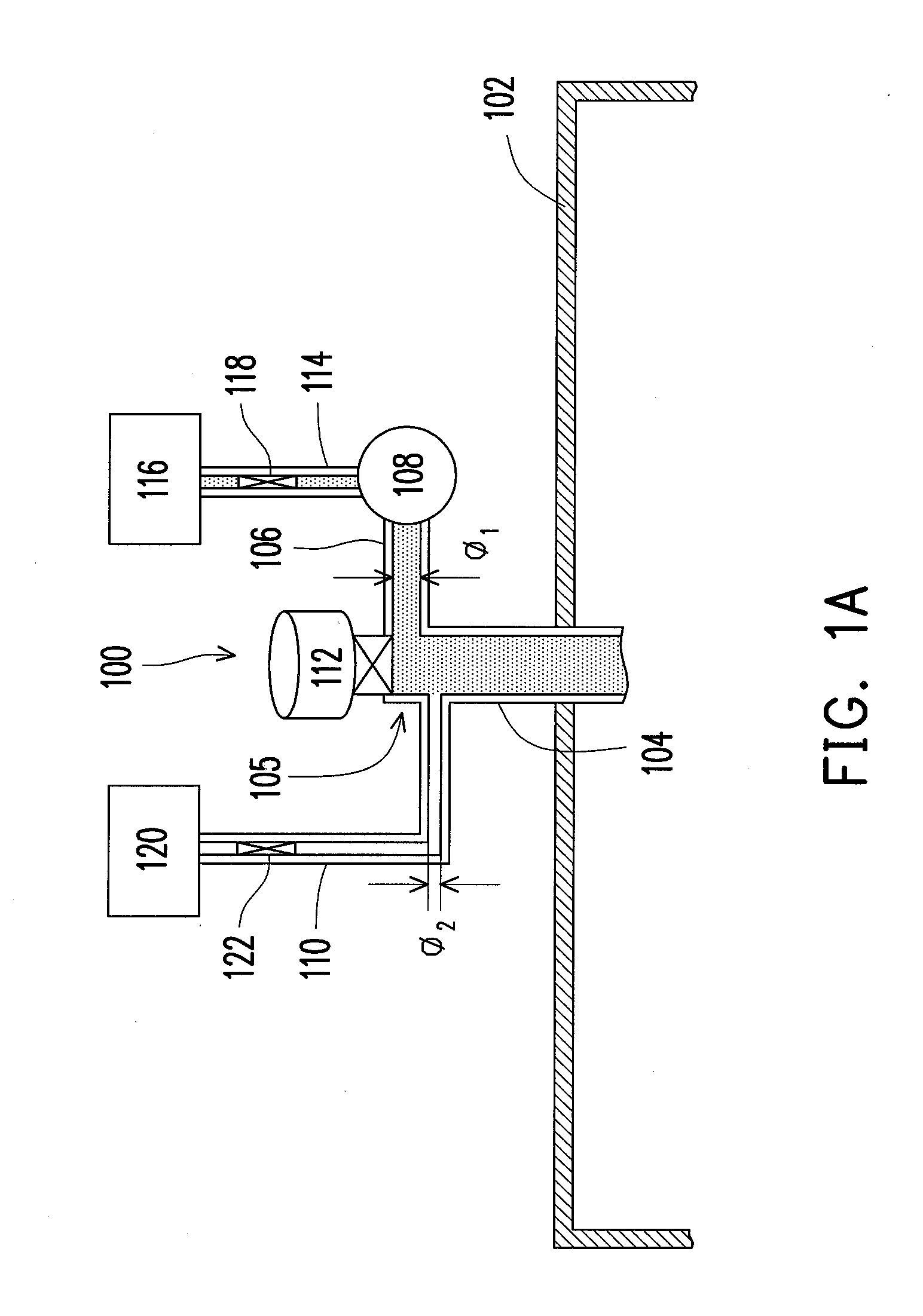
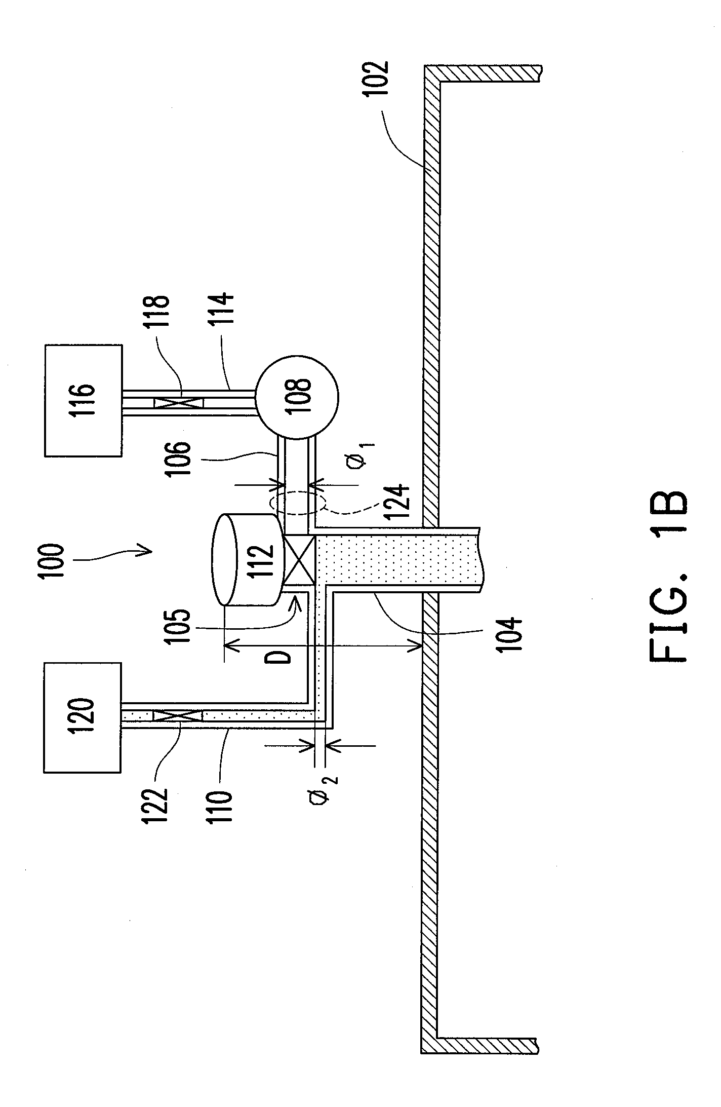
[0017]FIG. 1A and FIG. 1B are schematic diagrams illustrating operations of a gas supply apparatus according to the disclosure.

[0018]Referring to FIG. 1A, the gas supply apparatus 100 of the first embodiment is used for introducing gases to a process chamber 102 of a plasma-enhanced chemical vapor deposition (PECVD) system. The gas supply apparatus 100 of FIG. 1 includes a gas inlet tube 104 extended from external of the process chamber 102 to internal thereof, a cleaning gas pipe 106, a remote plasma source (RPS) 108, a process gas pipe 110, and a variable valve 112. The gas inlet tube 104 is, for example, located at a position±30% from a center of the process chamber 102, and preferably at a position±10% from the center of the process chamber 102. It should be noticed that if the process chamber 102 is a chamber of a large area PECVD system, a plurality of gas inlet tubes 104 are generally used. Thus, the above position of the gas inlet tube 104 is merely suitable for the use of s...

second embodiment

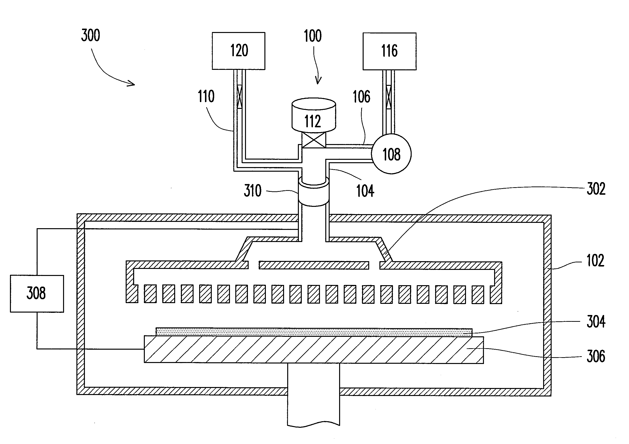
[0026]Besides the PECVD system 300 of the second embodiment, the persons having ordinary skill in the art should understand that the gas supply apparatus 100 can also be applied to other PECVD systems. Therefore, application of the gas supply apparatus 100 is not limited to the aforementioned embodiment.

[0027]In summary, in the gas supply apparatus of the disclosure, the process gas and the cleaning gas came from the RPS are introduced to the process chamber through a single inlet tube, and a variable valve is installed to prevent generating a parasitic capacitance or a situation that a plenty of films and dusts while thin-film deposition, so as to avoid an abnormal filming phenomenon generated at a passage between the cleaning gas pipe and the gas inlet tube due to the parasitic capacitance. Moreover, since the RPS is used in the gas supply apparatus of the disclosure, a cleaning efficiency can also be improved.


PUM

PropertyMeasurementUnit
frequencyaaaaaaaaaa
frequencyaaaaaaaaaa
frequencyaaaaaaaaaa

Abstract

A gas supply apparatus for introducing gases to a process chamber of a PECVD system is provided. The gas supply apparatus includes a gas inlet tube, a process gas pipe, a cleaning gas pipe, a remote plasma source (RPS) and a variable valve. The RPS is connected with a cleaning gas source, and the cleaning gas pipe is connected between the gas inlet tube and the RPS for introducing a cleaning gas from the RPS to the gas inlet tube. The process gas pipe is connected between the gas inlet tube and a process gas source for introducing a process gas to the gas inlet tube. The variable valve is installed in the gas inlet tube for closing a passage between the cleaning gas pipe and the gas inlet tube to prevent the process gas entering the cleaning gas pipe when the process gas is introduced to the process chamber.

Description

CROSS-REFERENCE TO RELATED APPLICATION[0001]This application claims the priority benefit of Taiwan application serial no. 98141043, filed on Dec. 1, 2009. The entirety of the above-mentioned patent application is hereby incorporated by reference herein and made a part of specification.BACKGROUND OF THE INVENTION[0002]1.Field of the Invention[0003]The present invention relates to a gas supply apparatus used for a high-frequency plasma-enhanced chemical vapor deposition (PECVD) system.[0004]2. Description of Related Art[0005]Presently, a plasma-enhanced chemical vapor deposition (PECVD) system is a most important and a main thin-film deposition process in a thin-film solar cell industry. All of film layers required by the thin-film solar cell can be fabricated by the PECVD system. Generally, in a process chamber of the PECVD system, processes of depositing thin-films on a substrate and cleaning the process chamber are performed. Therefore, at least a process gas used for the thin-film...

Claims


Application Information

Patent Timeline
Patent Type & Authority Applications(United States)
IPC IPC(8): C23C16/505C23C16/00
CPCC23C16/4405
Inventor SUN, HSIANG-PINGCHEN, YU-FANLO, SHUN-YUANHUNG, KAI-HSIANGWU, HSING-HUA
Owner IND TECH RES INST
Why Eureka
Try Eureka