Structure of bus bar assembly

a technology of bus bars and assembly parts, which is applied in the direction of bus-bar installation, substation/switching arrangement details, electric cable installation, etc., can solve the problems of increasing the amount of resin materials, requiring a complicated mold structure, and difficulty in keeping, so as to reduce the resistance of insulation, ensure orientation stability, and prolong the creepage distance

Active Publication Date: 2011-06-02
DENSO CORP
View PDF8 Cites 20 Cited by
  • Summary
  • Abstract
  • Description
  • Claims
  • Application Information

AI Technical Summary

Benefits of technology

[0011]It is another object of the invention to provide an improved structure of a bus bar assembly which is designed to keep the positional relation between a first and a second bus bar constant and have a good heat dissipation ability, and which may be manufactured in a simple manner and at a decreased cost.
[0021]The boss extends above a thickness of the second bus bar. The formation of the front opening results in concern about a decrease in resistance of insulation between the first and second bus bars, but however, the boss lengthens the creepage distance between the first and second bus bars, thereby ensuring the desired resistance of insulation between the first and second bus bars.

Problems solved by technology

It is, however, difficult to keep the first and second bus bars 91 and 92 simultaneously in place in the mold, thus requiring a complicated structure of the mold to do so.
The complete covering of the first and second bus bars 91 and 92 will result in an increase in amount of resin material, which leads to an increase in entire production cost of the bus bar assembly 9.
This requires pieces of the mold to be drawn in four different directions K1, K2, K3, and K4 after resin material is solidified in the mold, thus resulting in a complicated structure of the mold.

Method used


Image

  • Structure of bus bar assembly
  • Structure of bus bar assembly
  • Structure of bus bar assembly

Examples


Embodiment Construction

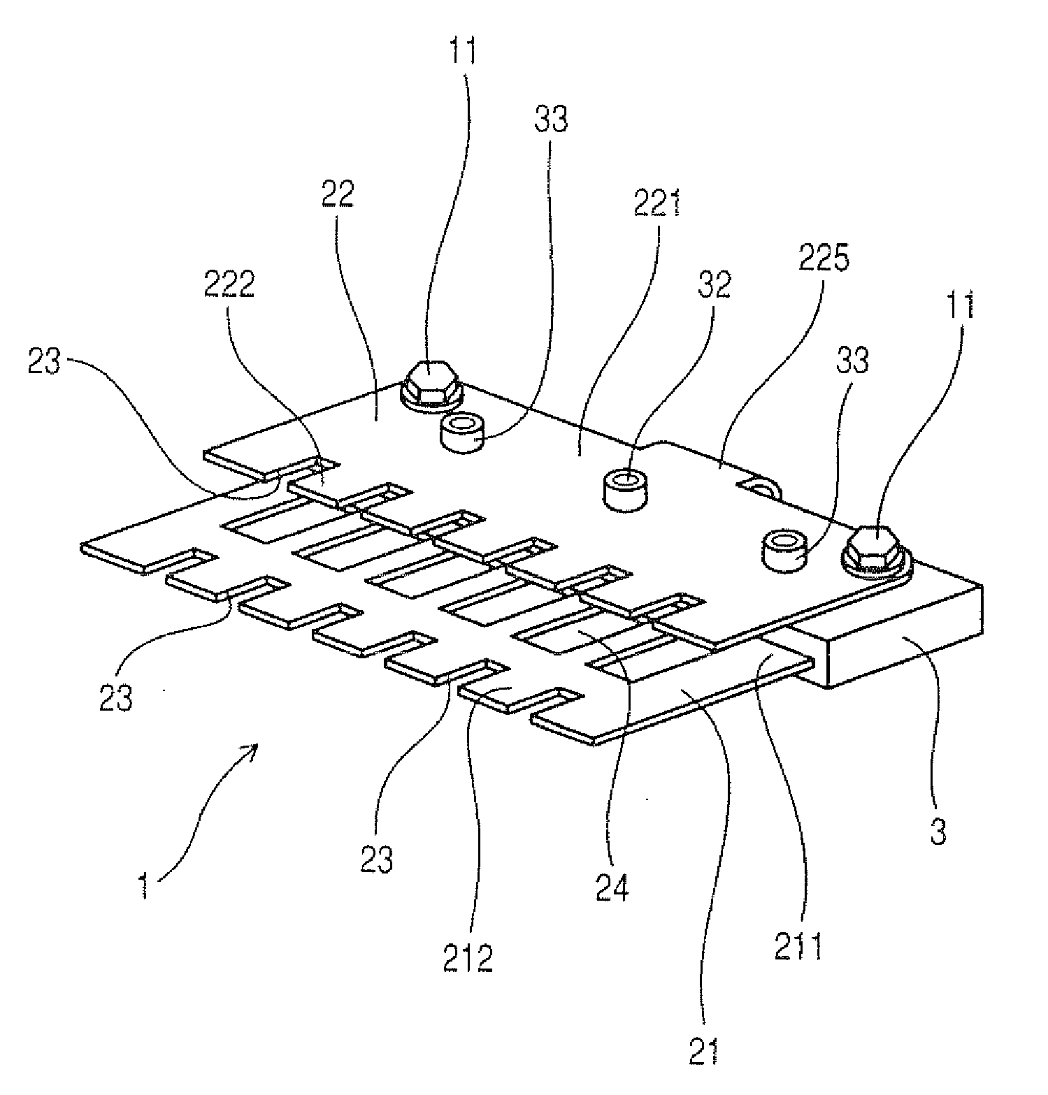
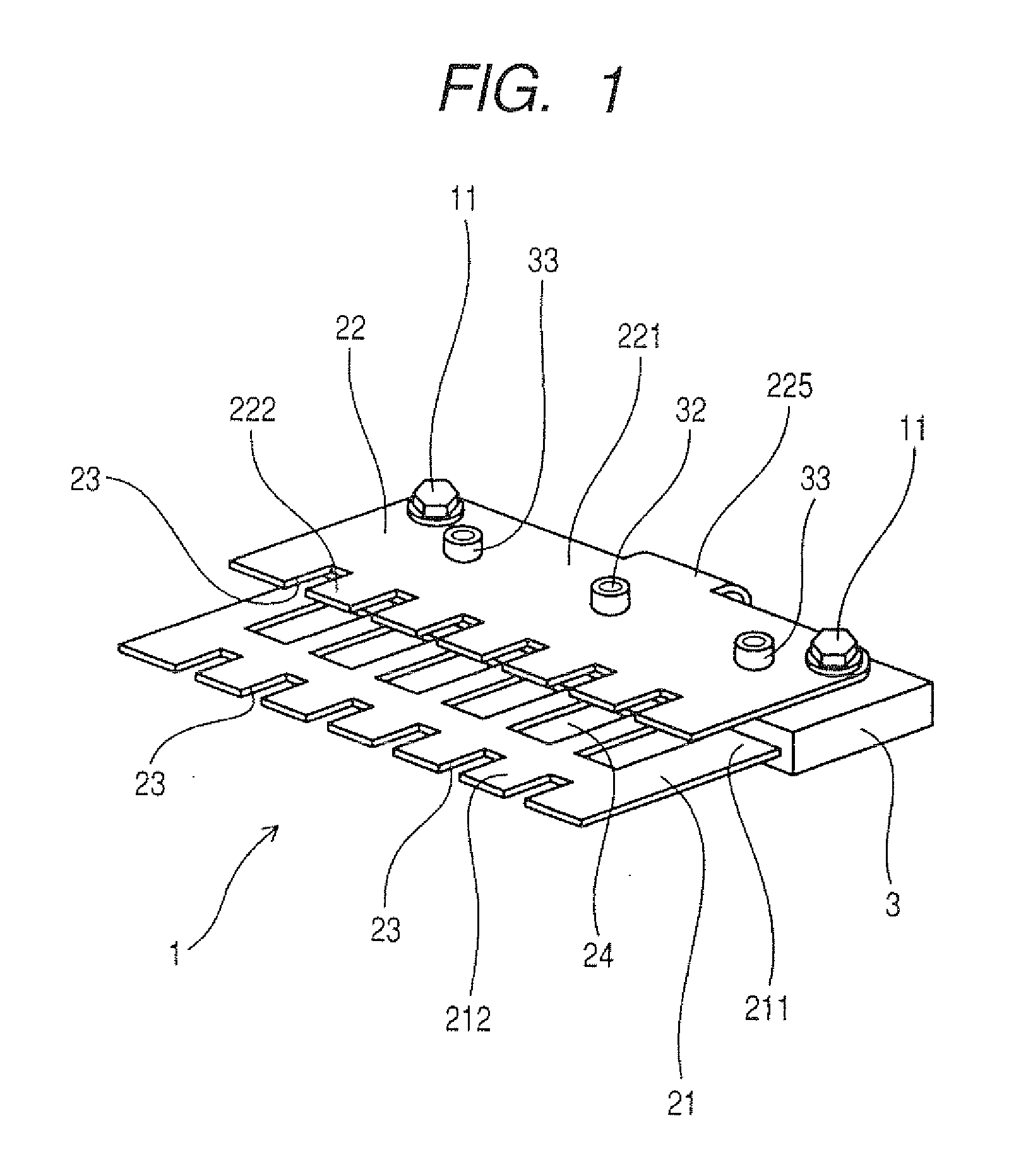
[0033]Referring to the drawings, wherein like reference numbers refer to like parts in several views, particularly to FIG. 5, there is shown a bus bar assembly 1 according to the present invention which may be employed to establish electric connections with a plurality of semiconductor modules installed in an electric power converter for use in electric vehicles or hybrid vehicles.

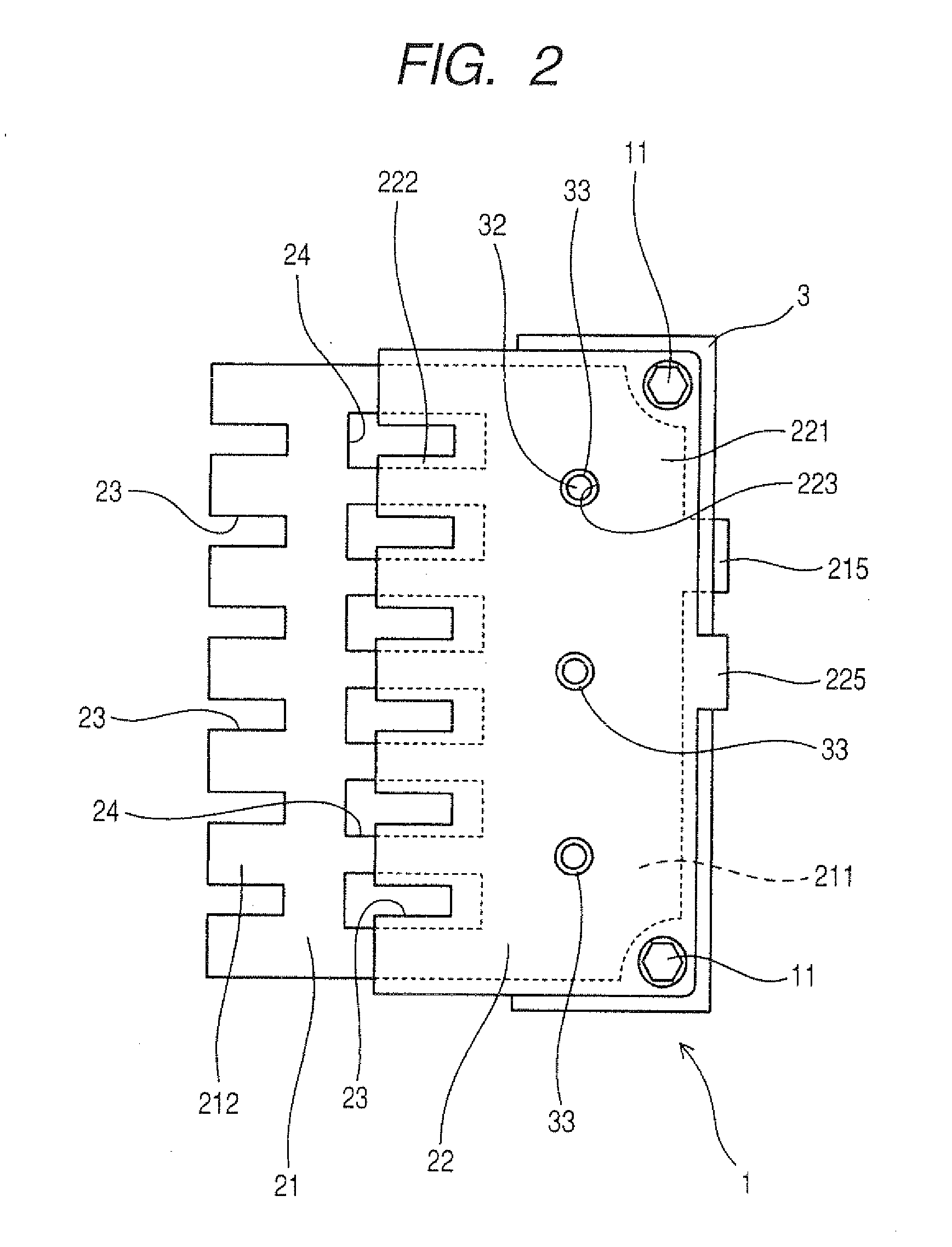
[0034]The bus bar assembly 1 includes a resin-molded body 3, a first bus bar 21, and a second bus bar 22. The first and second bus bars 21 and 22 are joined to main electrode terminals 41 of a plurality of semiconductor modules 4 installed in an electric power converter 40. Each of the semiconductor modules 4 is equipped with semiconductor devices. Each of the first and second bus bars 21 and 22 is made of a conductive flat plate.

[0035]The first bus bar 21, as shown in FIGS. 1, 2, and 5, consists of a plate body 211 and a plurality of connecting terminals 212 extending from the side of the plate body 211 i...


PUM


Abstract

A bus bar assembly used for establish electric connections with semiconductor modules of an electric power converter. The bus bar assembly includes a resinous body, a first and a second bus bar to which terminals of the semiconductor modules are to be connected. Each of the first and second bus bars includes a plate body and a plurality of connecting terminals extending from the plate body substantially in parallel to a major surface of the plate body. At least a portion of the body plate of the first bus bar is disposed inside the resinous body. The second bus bar is mounted at the plate body on the resinous body and laid to overlap the first bus bar at a given distance away from the first bus bar. This structure minimizes the misalignment between the first and second bus bars after the resinous body is formed.

Description

CROSS REFERENCE TO RELATED DOCUMENT[0001]The present application claims the benefit of priority of Japanese Patent Application No. 2009-269800 filed on Nov. 27, 2009, the disclosure of which is incorporated herein by reference.BACKGROUND OF THE INVENTION[0002]1. Technical Field of the Invention[0003]The present invention relates generally to a bus bar assembly equipped with a first and a second bus bar which are made of a flat strip and to which main electrode terminals of a plurality of semiconductor modules installed in an electric power converter are joined.[0004]2. Background Art[0005]Electric power converters such as inverters installed in electric vehicles or hybrid vehicles are usually equipped with a first and a second bus bar which are made of a flat strip and to which main electrode terminals of a plurality of semiconductor modules are coupled. For instance, the first bus bar is connected to a positive (+) electrode of a dc power supply. The second bus bar is connected to ...

Claims


Application Information

Patent Timeline
Patent Type & Authority Applications(United States)
IPC IPC(8): H02G5/00
CPCH02M7/003
Inventor GOTOU, YUKIO
Owner DENSO CORP
Why Eureka
Try Eureka