Method for manufacturing molded foam

a manufacturing method and foam technology, applied in the field of molding foam manufacturing, can solve the problems of affecting the service life of the roof air conditioner, the duct can break and scatter, and the cost is a problem, and achieve the effects of improving the expansion ratio, reducing weight, and excellent impact resistan

Inactive Publication Date: 2011-06-02
KYORAKU CO LTD
View PDF8 Cites 14 Cited by
  • Summary
  • Abstract
  • Description
  • Claims
  • Application Information

AI Technical Summary

Benefits of technology

[0004]It is possible to improve the functionalities of such an air-conditioner duct by adjusting the foamed state.
[0026]According to method of manufacturing of foam mentioned above under (3), foam having expansion ratio above 2-5 times and impact strength above 70 Kg. cm can be produced at low cost.BRIEF DESCRIPTION OF THE DRAWINGS

Problems solved by technology

For instance, in the roof side air-conditioner duct of vehicles, if a curtain air bag to protect the passengers from side shock spreads out based on the force of pressure gas, a roof side air-conditioner duct can break and scatter due to impact at the time of spreading out.
Moreover, simultaneously with using expensive polypropylene for foaming such as polypropylene having long chain branching structure in large quantity, and mixing expensive impact resistant material such as linear low density polyethylene (LLDPE) etc, it is possible to have foammolding that has high expansion ratio and high impact resistance but cost is a problem.

Method used


Image

  • Method for manufacturing molded foam
  • Method for manufacturing molded foam
  • Method for manufacturing molded foam

Examples


working examples

[0066]In the following lines, the exemplary embodiments have been explained based on Working and Comparative examples, but the present invention is not restricted to these examples.

[0067]First, propylene homopolymer (PP1, PP2), propylene ethylene block copolymer (PP3) and low density polyethylene (LDPE) used as working and comparative examples are as follows.[0068]PP1: Bolearis Co., Product Name Daploi (WB130)[0069]PP2: Bolearis Co., Product Name Daploi (WB135)[0070]PP3: Japan polypropylene Co. Ltd., Product Name “New Former” (FB 3312)[0071]LDPE: Sumitomo Chemical Co. Ltd., Product Name “Sumikasen” (F108-1)

[0072]Further, MT (Melt Tension) at 230° C. (gf), MFR (Melt Flow Rate) at 230° C. (g / 10 min.), MT×MFR value (gf·g / 10 min.), Tensile Elastic Modulus (MPa) at 23° C. and Tensile Rupture Elongation (%) in these resins have been indicated in Table 1.

[0073]Further, MT denotes the tension when melt tension tester (Toyo Precision Machines Ltd.) is used and strand is extruded from orifice...

working example 1

[0077]PP1 60 wt %, PP3 10 wt %, LDPE 30 wt % were mixed and used as the base resin.

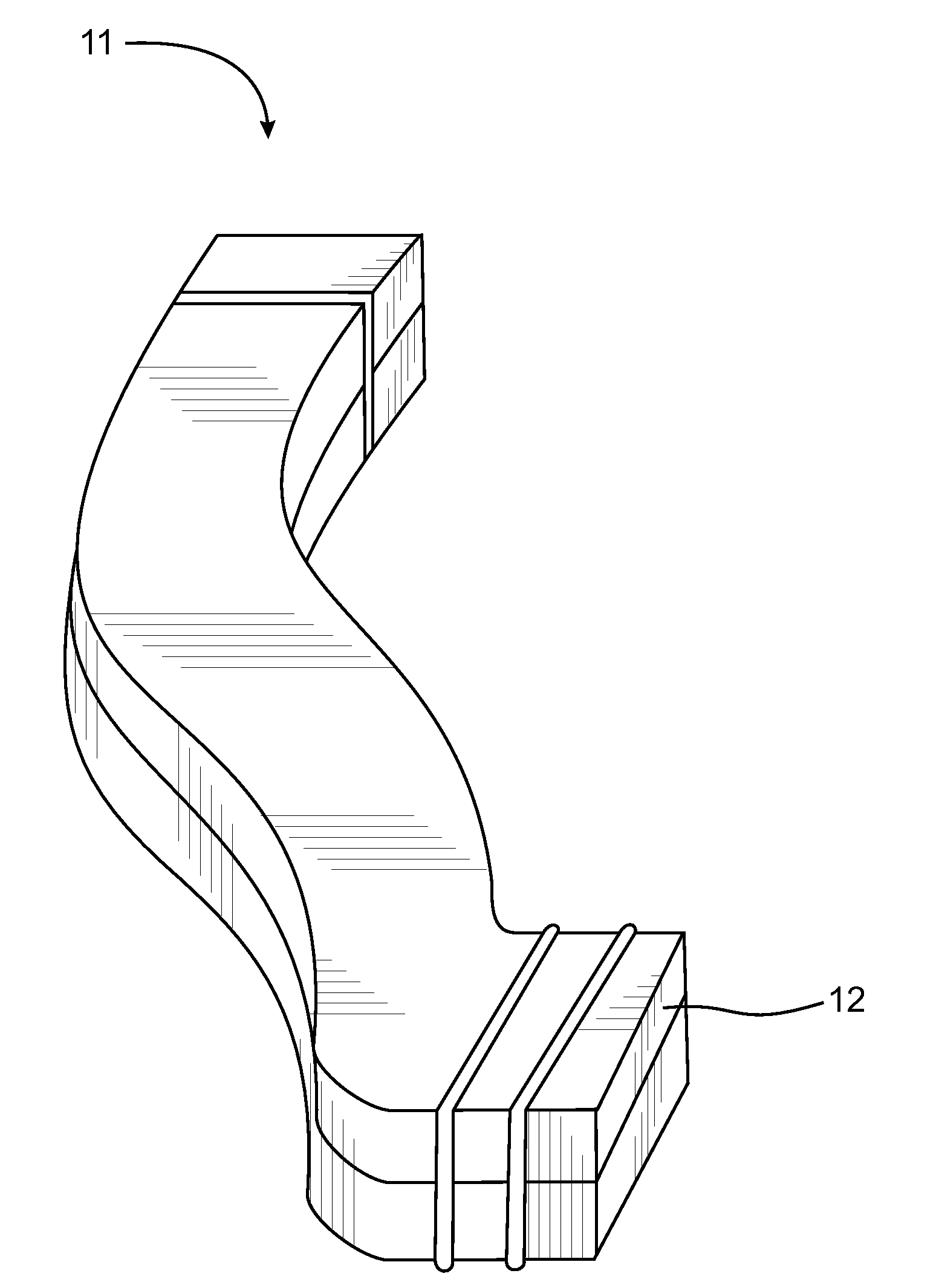
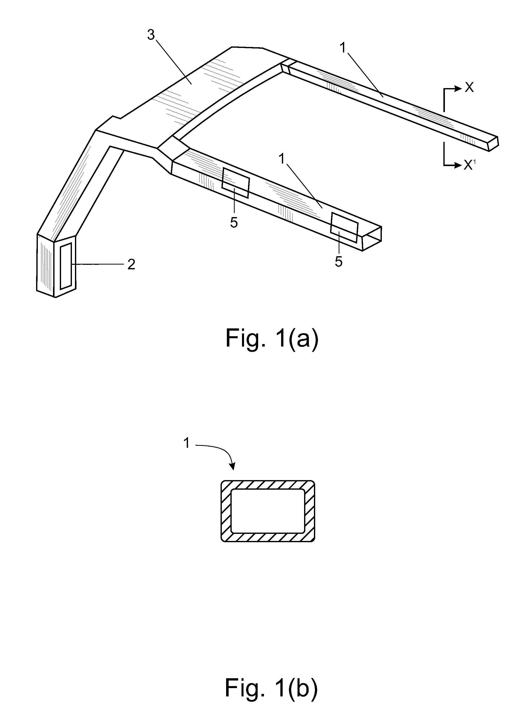
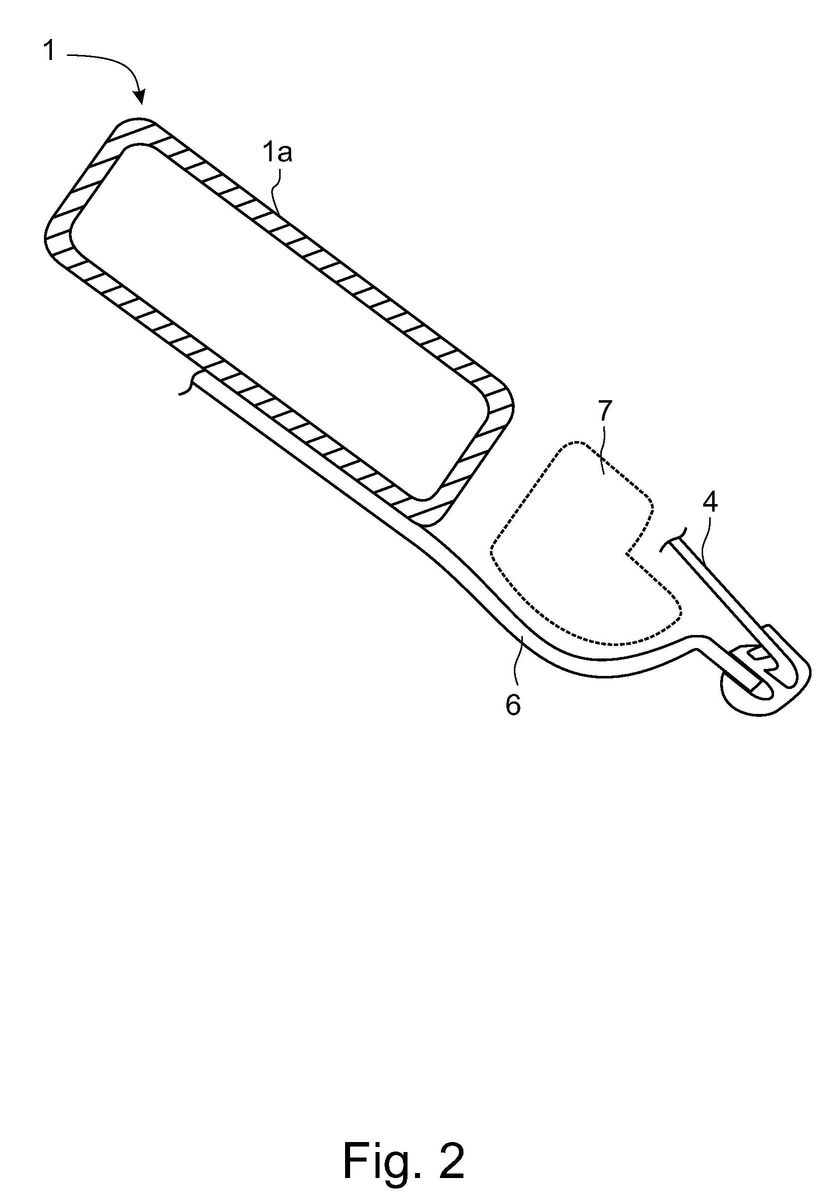
[0078]Next, to this base resin, super critical state nitrogen was added as blowing agent, 60 wt % talc master batch 1.5 weight parts as nucleophile and 40 wt % carbon black master batch 1.5 weight parts as coloring agent and blown to obtain foaming resin. After mixing it in the extruder, it was stored in accumulator in the die—the cylindrical space between mandrel and die external cylinder and using ring like piston, it was extruded to split die as cylindrical parison and after closing the die, blow molded sample was obtained by blowing air at pressure 0.1 MPa in parison.

working example 2

[0079]PP1 40 wt %, PP3 15 wt % and LDPE 45 wt % were mixed and used as the base resin.

[0080]Other processes were same as example 1 to obtain the blow molded sample.


PUM

PropertyMeasurementUnit
melt tensionaaaaaaaaaa
melt flow rateaaaaaaaaaa
weightaaaaaaaaaa

Abstract

A method for manufacturing molded foam which uses cheap materials, is light in weight and which is excellent in impact resistance. In the method for manufacturing molded foam, propylene homopolymer with a long chain branch, propylene ethylene block copolymer and low density polyethylene are mixed in the base resin at a prescribed mixing ratio. A blowing agent is added to carry outfoaming. A prescribed mixing ratio is determined based on the value arrived at by a multiplying melt tension of each material mixed with the melt flow rate and the Tensile Rupture Elongation.

Description

FIELD OF THE INVENTION[0001]This invention is concerning a method for manufacturing molded foam used in a light weight air conditioner duct for vehicles.BACKGROUND AND SUMMARY OF THE INVENTION[0002]An air-conditioner duct for vehicles to ventilate the air-conditioner air supplied by the air-conditioner unit to the desired part is known.[0003]Since light-weight and insulation are essential in such an air-conditioner duct, normally foamed resin molding is used.[0004]It is possible to improve the functionalities of such an air-conditioner duct by adjusting the foamed state.[0005]For instance, in order to provide the duct with sound absorption or noise deadening effect, hollow molding whose inner surface is de-foamed (Refer to Patent Document 1), duct with specified surface hardness and bubble deformation ratio (Refer to Patent Document 2), Foam duct with specific surface roughness to prevent condensation on the outer surface of the air-conditioner duct (Refer to Patent 3), air duct for...

Claims


Application Information

Patent Timeline
Patent Type & Authority Applications(United States)
IPC IPC(8): C08J9/06
CPCC08J9/0061C08J2423/00C08J2323/12
Inventor ONODERA, MASAAKISUMI, TAKEHIKOTAMADA, TERUOIGARASHI, YUOHNO, YOSHINORI
Owner KYORAKU CO LTD
Why Eureka
Try Eureka