Display system for higher grayscale with a varying light source

a technology of light source and display system, applied in the field of image display system, can solve the problems of most conventional display system, limited and difficult, adverse effects on image quality, etc., and achieve the effect of improving configuration and control methods, without cost penalty, and sacrificing brightness

Inactive Publication Date: 2011-06-02
SILICON QUEST KABUSHIKI KAISHA +1
View PDF6 Cites 10 Cited by
  • Summary
  • Abstract
  • Description
  • Claims
  • Application Information

AI Technical Summary

Benefits of technology

[0046]It is an aspect of the present invention to disclose improved configuration and control methods to provide a display system that implements a digitally controlled SLM to achieve display images with a 16 bit grayscale without cost penalty and without sacrificing brightness.
[0047]In view of achieving the image display quality with a 16-bit grayscale, it is an aspect of the present invention is to provide an image display system using a spatial light modulator (SLM), such as a micro-mirror device, to display an image with a greater number of gray scales without requiring the SLM to operate at an excessively fast speed with increased number of repetitive operations of the SLM and without sacrificing brightness as much as “Light Intensity Grayscale Control” or “Light Width Grayscale Control” such that the above discussed problems and limitations can be resolved.
[0048]The image display system according to one aspect of the invention includes an illumination light projected from a light source controlled by a light source control unit to adjust the illumination intensity and / or light emission time of the illumination light as a combination of Time Domain Grayscale Control (hereafter TDGC) and Light Intensity Grayscale Control (hereafter LIGC) and / or Light Width Grayscale (hereafter LWGC) so as to maximize the levels of grayscale and minimizing the loss of illumination light energy by the maximum utilization of TDGC as much as the Bit Time (the minimum controllable time of SLM) allows and the utilization of LIGS or LWGC for the rest of the least significant data bits.
[0049]It is another aspect of the present invention when the light source controller does not have enough high speed driving capability, twice longer time slice can be used than Bit Time to repeat and vary the intensity of light source. Although the loss of light energy will increase compared with the case using Bit Time, the requirement of circuit will be reduced
[0050]As shown above, this invention can provide significantly higher grayscale with almost same brightness and the same data transfer speed compared with the conventional PWM.

Problems solved by technology

Even though there are significant advances of the technologies in implementing an electromechanical mirror device as a spatial light modulator (SLM) in recent years, there are still limitations and difficulties when it is employed to provide a high quality image.
Specifically, when the images are digitally controlled, the image quality is adversely affected due to the fact that the images are not displayed with sufficient levels of gray scales.
As described above, the ON-and-OFF states of a micromirror control scheme as that implemented in U.S. Pat. No. 5,214,420 and by most conventional display systems limits display quality.
Due to the ON-OFF states implemented in conventional systems, there is no way to provide a shorter
The limited gray scale leads lower image quality.
This speed is not easy to achieve even with the latest technology without costly circuit.
As shown, both LWGC and LIGC are attractive for slower data transfer circuits, but the loss of the brightness is significant and loses as much as ⅔ of the available brightness.
The quality of an image display is limited due to the limited number of gray scales.
Since the mirror is controlled to operate in an either ON or OFF state, the conventional image display apparatuses have no way to provide a pulse width to control the mirror that is shorter than the control duration allowable according to the LSB.
The limited gray scale due to the LSB limitation leads to a degradation of the quality of the display image.
That leads to the degradations of display image qualities.
The artifacts are caused by a technical limitation that the digitally controlled image does not obtain sufficient number of the gray scale, i.e. the levels of the quantity of light.
The mirrors produced by applying the CMOS technologies probably is not appropriate for operating the mirror at such a high range of voltages, and therefore the DMOS mirror devices may be required.
Conventional mirror controls are therefore faced with a technical problem that higher level of gray scales and can only be achieved by operating the micromirrors at a range of higher voltage to maintain the benefits of manufacturing a smaller image display apparatus.
However, these patents or patent applications do not provide an effective solution to attain a sufficient number of the gray scale in the digitally controlled image display system.
However, these inventions do not provide a direct solution for a person skilled in the art to overcome the above-discussed limitations and difficulties.
The major difficulty that hinders the increase of the gray scales of image display is caused by the ON-OFF control scheme of the conventional systems that limits the minimum ON time to adjust the brightness of a display image.
There is no way to provide the adjustable brightness that is lower than the step by controlling the micromirrors.
This speed is not easy to achieve even with the latest technology without costly circuit.
However, the present technology does not allow inexpensively higher level of grayscale using Time Domain Grayscale Control than 8 bits.

Method used


Image

  • Display system for higher grayscale with a varying light source
  • Display system for higher grayscale with a varying light source
  • Display system for higher grayscale with a varying light source

Examples


Embodiment Construction

[0071]Reference is now made to the above listed Figures for the purpose of describing, in detail, the preferred embodiments of the present invention. The Figures referred to and the accompanying descriptions are provided only as examples of the invention and are not intended in anyway to limit the scope of the claims appended to the detailed description of the embodiment.

Outline of Projection Display System

[0072]The following detail description is provided for an exemplary embodiment of the present invention by referring to the accompanying drawings.

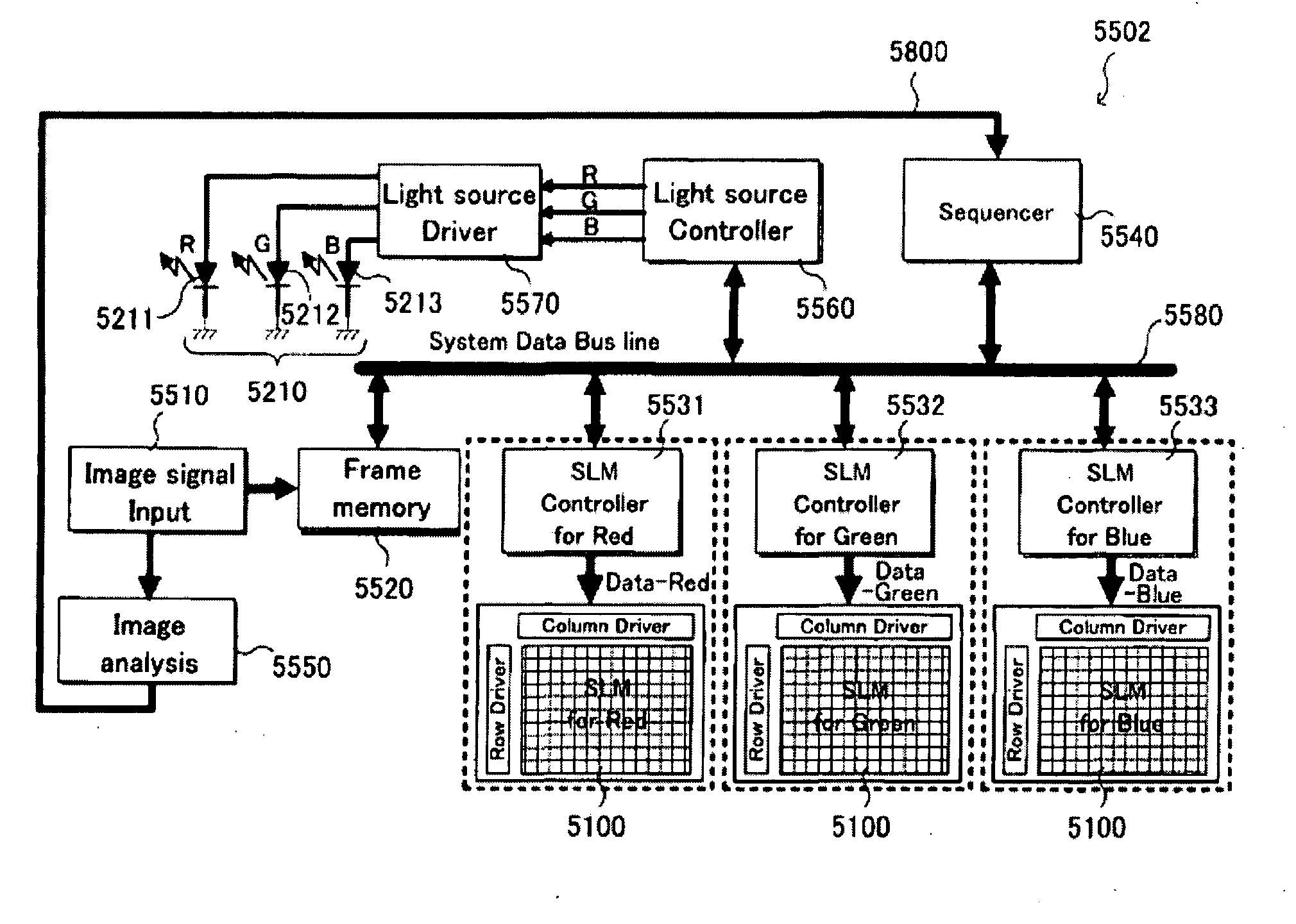
[0073]FIG. 6 is a functional block diagram for showing the configuration of a projection apparatus according to a preferred embodiment of the present invention.

[0074]FIG. 6 shows a projection apparatus 5010 according to the present embodiment comprises a single spatial light modulator (SLM) 5100, a control unit 5500, a Total Internal Reflection (TIR) prism 5300, a projection optical system 5400, and a light source optical system 5200.

[00...


PUM


Abstract

The present invention provides a projection apparatus that includes:at least one spatial light modulator (SLM) and at least one variable light source and at least one control unit controlling said SLM and / or said light source and said SLM has a minimum controllable time period and said control unit controls said SLM providing said minimum controllable time periods of the modulation of said SLM at least twice in a frame period and said control unit controls said light source during said minimum controllable time periods.

Description

CROSS REFERENCE TO RELATED APPLICATIONS[0001]This application is a Non-provisional Application of a Provisional Application 61 / 398,813 filed on Jul. 1, 2010. The Provisional Application 61 / 398,813 and this application is a Continuation in Part (CIP) Application of a U.S. patent application Ser. No. 12 / 286,838 filed on Oct. 1, 2008 and application Ser. No. 11 / 893,696 filed on Aug. 23, 2007 now issued as U.S. Pat. No. 7,492,378. The disclosures made in these patent applications including 61 / 398,813, Ser. No. 12 / 286,838, and Ser. No. 11 / 893,696 are hereby incorporated by reference in this patent application.BACKGROUND OF THE INVENTION[0002]1. Field of the Invention[0003]The present invention relates to an image display system that modulates the illumination light transmitted from a light source according to image signals for projecting and displaying images. More particularly, this invention relates to an image display system implemented with a light source controlled to project light ...

Claims


Application Information

Patent Timeline
Patent Type & Authority Applications(United States)
IPC IPC(8): G02B26/00
CPCG02B26/0841G02B27/1026G09G3/346G09G3/2011G02B27/1033
Inventor ISHII, FUSAO
Owner SILICON QUEST KABUSHIKI KAISHA
Why Eureka
Try Eureka