Fuel pump

a fuel pump and pump body technology, applied in the direction of liquid fuel engines, machines/engines, positive displacement liquid engines, etc., can solve the problems of adversely affecting the next instance of engine starting, and achieve the effects of preventing fuel leakage, reducing fuel pressure, and high discharge efficiency

Inactive Publication Date: 2011-06-02
TOYOTA JIDOSHA KK
View PDF12 Cites 37 Cited by
  • Summary
  • Abstract
  • Description
  • Claims
  • Application Information

AI Technical Summary

Benefits of technology

[0026]With the present invention, a configuration is provided in which it is possible to obstruct a micro gap provided in order to reduce the fuel pressure on the pump discharge side when the pump is stopped, and the back-flow of fuel through the micro gap can be prevented by obstruct

Problems solved by technology

In such a situation, there is concern that the presence of fuel that has leake

Method used


Image

  • Fuel pump
  • Fuel pump
  • Fuel pump

Examples


embodiment 1

Fuel Supply System

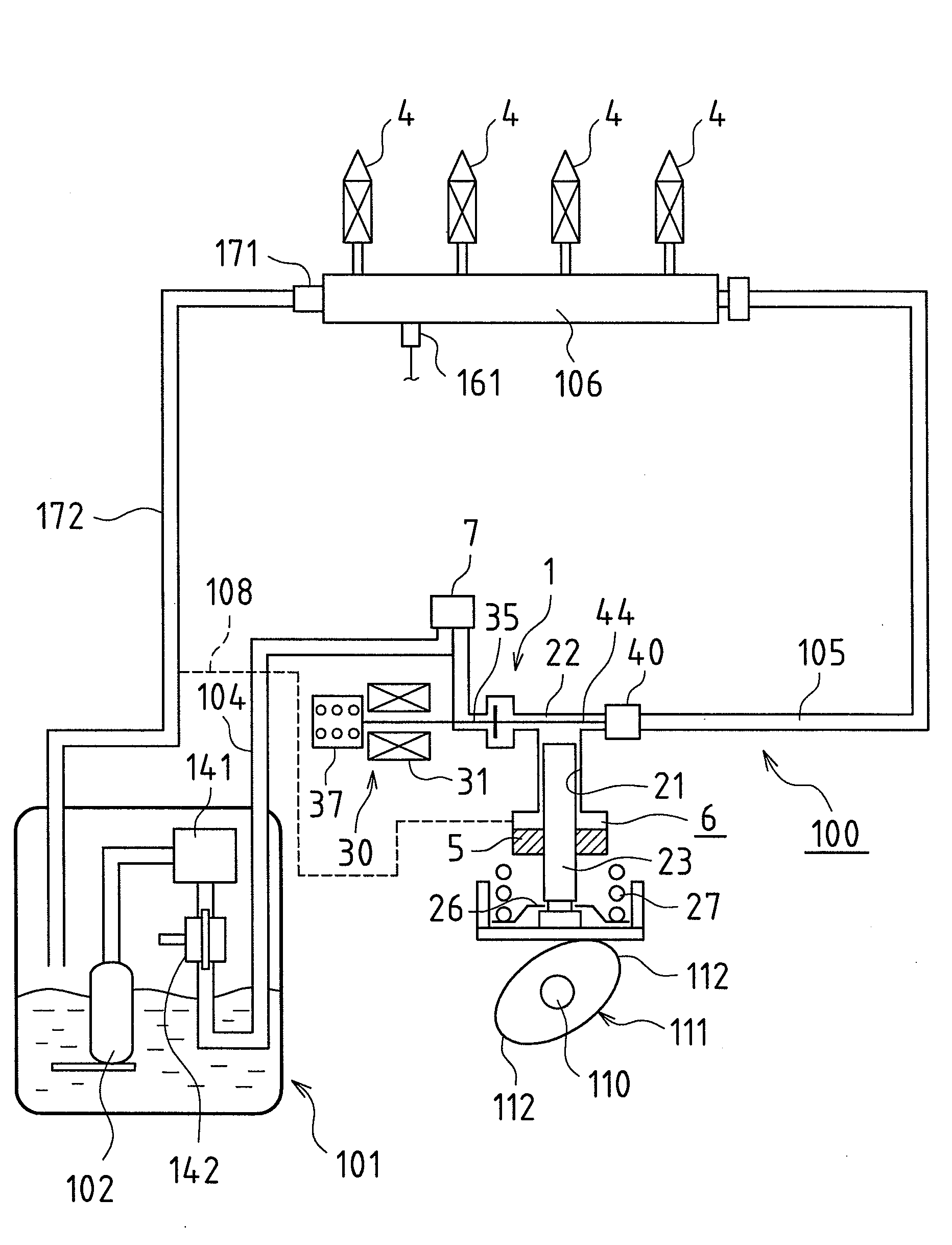
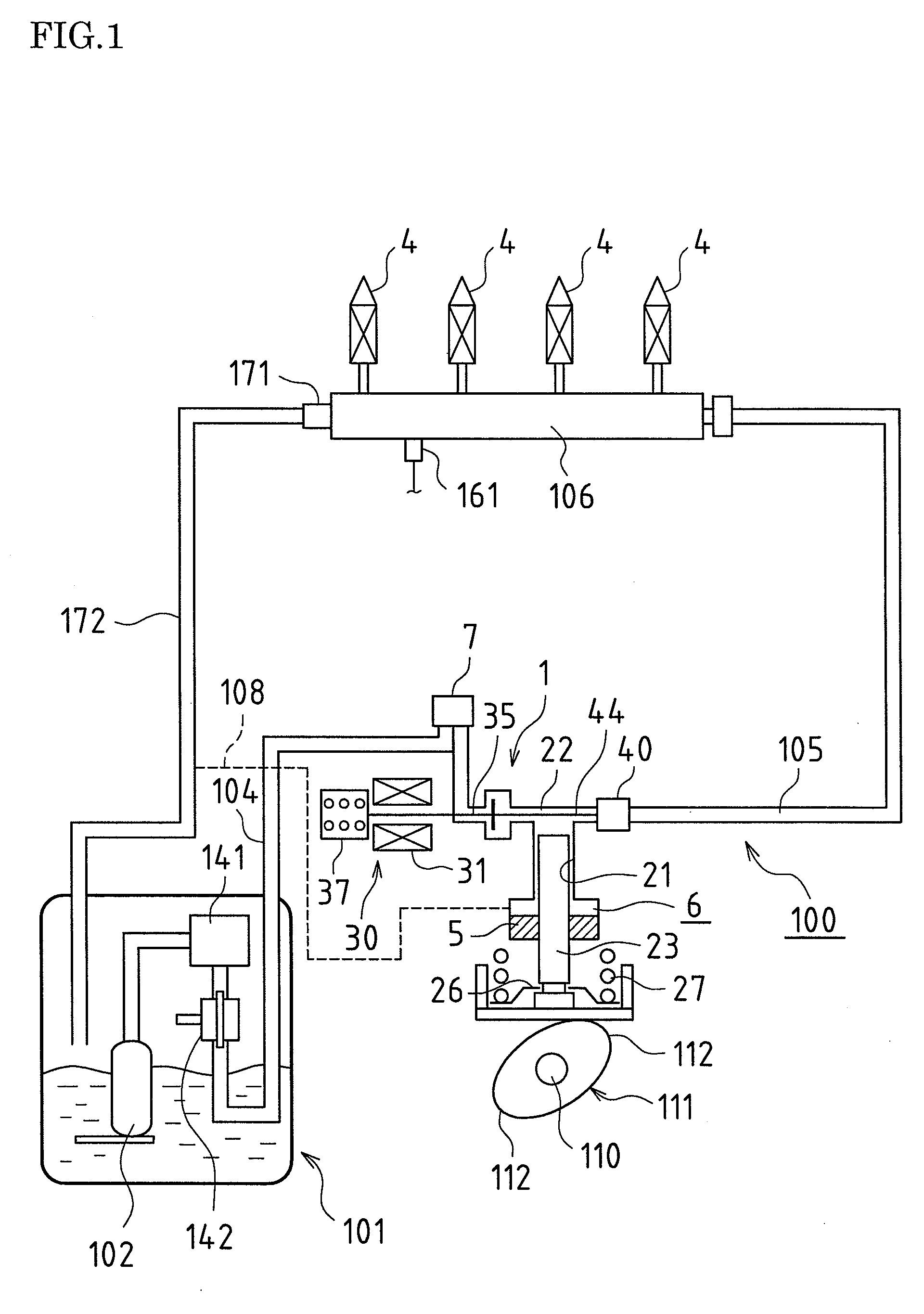
[0034]FIG. 1 is a diagram schematically showing the structure of a fuel supply system 100 in the present embodiment. As shown in FIG. 1, the fuel supply system 100 includes a feed pump 102 composed of an electric pump that pumps outs fuel from a fuel tank 101, and a high pressure fuel pump 1 that compresses the fuel pumped out by the feed pump 102 and discharges the compressed fuel to injectors (fuel injection valves) 4 in cylinders (four cylinders).

[0035]In terms of basic configuration (a specific configuration is described later with reference to FIG. 3), the high pressure fuel pump 1 includes a cylinder 21, a plunger 23, a compression chamber 22, and an electromagnetic spill valve 30. The plunger 23 is driven by the rotation of a drive cam 111 that is attached to an exhaust cam shaft 110 in the engine, and the plunger 23 reciprocates in the cylinder 21. The volume of the compression chamber 22 expands and contracts due to the reciprocation of the plunger 23. In ...

embodiment 2

[0072]Next is a description of Embodiment 2. The electromagnetic spill valve 30 of the high pressure fuel pump 1 in Embodiment 1 described above is a so-called “normally open” type of valve that opens due to the biasing force of the coil spring 37 when electrical conduction to the electromagnetic solenoid 31 is stopped.

[0073]Instead, the present embodiment describes the case in which the present invention has been applied to a high pressure fuel pump 1 that includes a so-called “normally closed” type of electromagnetic spill valve 30 that closes when electrical conduction to the electromagnetic solenoid 31 is stopped. In other words, the high pressure fuel pump 1 according to the present embodiment is configured such that biasing force in the valve closing direction is applied to the intake valve 35 of the electromagnetic spill valve 30 by a coil spring or the like, and furthermore is configured such that when electricity is conducted to the electromagnetic solenoid 31, the intake v...

embodiment 3

[0079]Next is a description of Embodiment 3.

[0080]In Embodiments 1 and 2 described above, when the high pressure fuel pump 1 is stopped, the needle valve 44 retreats from the opening 42b of the valve element 42, and a micro gap is constantly formed between the inner edge portion of the opening 42b and the tip portion of the needle valve 44.

[0081]Instead, in the present embodiment, at the time when the high pressure fuel pump 1 has switched from the drive state to the stopped state, the needle valve 44 is caused to retreat from the opening 42b of the valve element 42, a micro gap is formed between the inner edge portion of the opening 42b and the tip portion of the needle valve 44, and at a predetermined timing, the opening 42b is obstructed by the needle valve 44, thus preventing the micro gap from being formed.

[0082]In other words, when the engine switches from the drive state to the stopped state, and the high pressure fuel pump 1 has stopped along with this, as shown in FIG. 5, t...


PUM


Abstract

In one embodiment, a small-diameter opening (42b) is formed in the central portion of a valve element (42) included in a check valve (40) of a high pressure fuel pump (1). A needle valve (44) is provided integrally with a valve element (35a) of an electromagnetic spill valve (30), and the opening (42b) of the valve element (42) can be opened and closed with a tip portion of the needle valve (44). When the high pressure fuel pump (1) switches from the drive state to the stopped state, the needle valve (44) retreats from the opening (42b) of the valve element (42) in conjunction with the movement of the valve element (35a) of the electromagnetic spill valve 30, thus forming a micro gap. When the high pressure fuel pump (1) is driven and the intake stroke is performed, the needle valve (44) obstructs the opening 42b of the valve element (42) in conjunction with the movement of the valve element (35a) of the electromagnetic spill valve 30, thus preventing the back-flow of fuel due to the existence of the micro gap.

Description

TECHNICAL FIELD [0001]The present invention is applicable to an internal combustion engine such as an in-cylinder direct injection engine, and relates to a fuel pump for supplying high pressure fuel to a fuel injection valve (injector). In particular, the present invention relates to a measure for improving the discharge efficiency of a fuel pump.BACKGROUND ART [0002]Conventionally, with an engine in which high pressure is required for fuel that is supplied to an injector, such as with an in-cylinder direct injection engine for example, fuel that has been pumped from a fuel tank is compressed by a high pressure fuel pump, and then supplied to the injector.[0003]Specifically, as disclosed in Patent Literature 1 below as well, a fuel supply system in this type of engine is configured so as to include a feed pump that pumps out fuel from the fuel tank, and a high pressure fuel pump that compresses the fuel that has been pumped out by the feed pump. Then, the fuel that has been compress...

Claims


Application Information

Patent Timeline
IPC IPC(8): F04B49/00
CPCF02M59/34F02M59/366F04B53/1085F04B1/0448F04B1/0456F02M59/462Y10T137/7738
Inventor SAKAI, MITSUTOAKITA, TATSUHIKOFURUHASHI, TSUTOMUOGURI, TATSUMI
Owner TOYOTA JIDOSHA KK
Why Eureka
Try Eureka