
Method for error handling for a control device for a passenger protection system and a control device for a passenger protection system

Inactive Publication Date: 2011-06-02
ROBERT BOSCH GMBH
View PDF3 Cites 3 Cited by
  • Summary
  • Abstract
  • Description
  • Claims
  • Application Information

AI Technical Summary

Benefits of technology

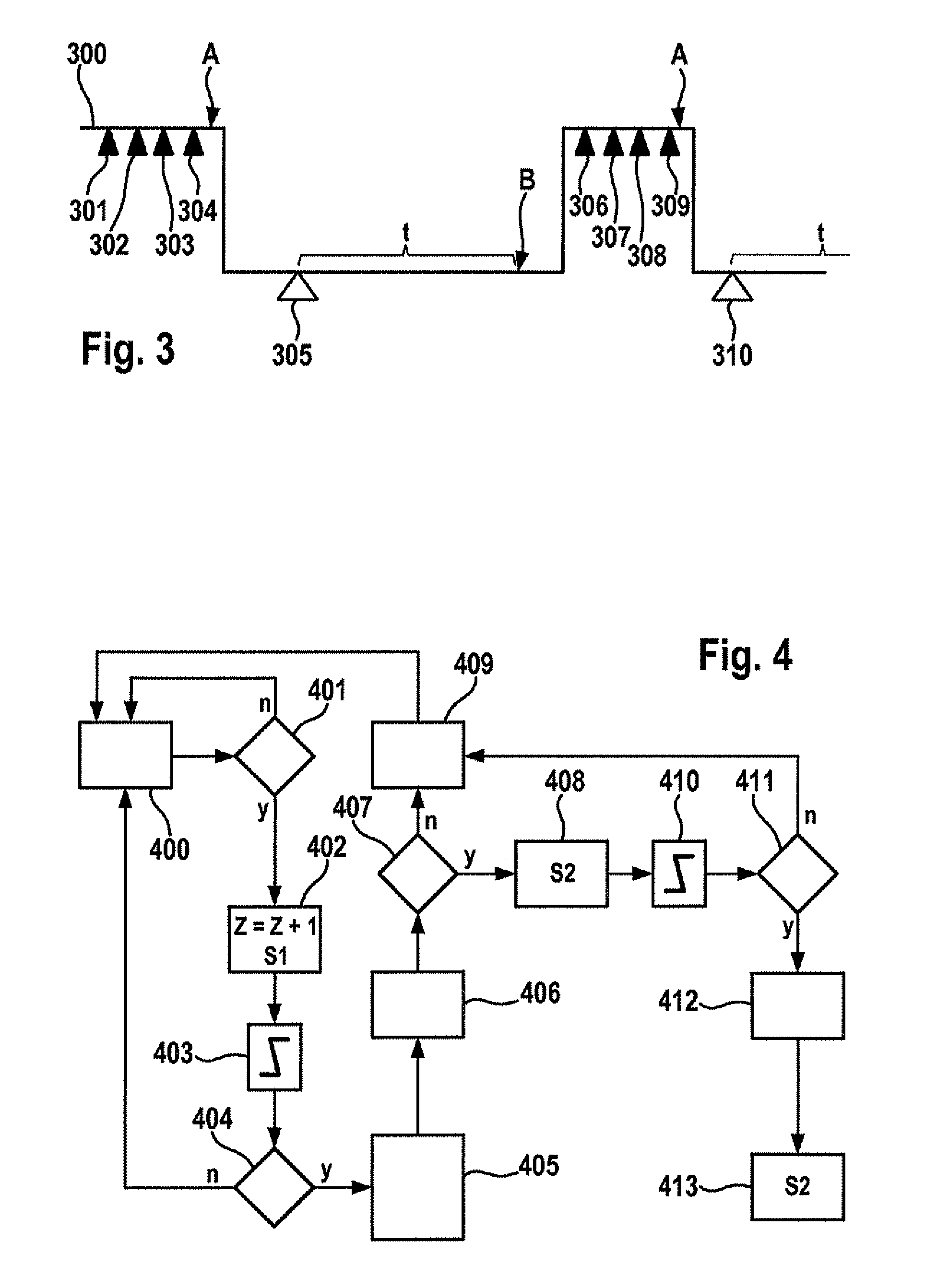
[0003]A method in accordance with the present invention for error handling for a control device for a passenger protection system and a control device for a passenger protection system have the advantage that immediately after an error is detected, at least one function in the control device is switched off and an error qualification occurs after this switching-off. The result of this is that the error qualification is robust; since the function is already switched off, time is not limited, by a maximum load of a hardware module that constitutes the function, for example. The immediate switching off also allows for this function loss to become transparent without time loss, since by switching off the function after the error detection, the function is stored in a memory, for example. Because this transparency of the function restriction is provided immediately, it may be archived in snapshots, for example, by a crash recorder. Nevertheless, the error qualification in accordance with the final error cause may take place in a robust manner. According to the present invention, the switching off is performed by the error handling circuit in the control device, and a switching mechanism in the error handling circuit ensures the corresponding sequence, namely that after the error detection, the at least one function is switched off and after this switching off, the error qualification is performed.
[0007]In the case at hand, the immediate switching off after the error detection means that when the error detection is complete and has resulted in the detection of an error, the switching off takes place immediately afterward. A short time interval possibly exists between the end of the error detection and the switching off.
[0013]The error detection may be implemented in the following advantageous way:
[0015]It is furthermore advantageous if the at least one first error type is stored in a first memory in the control device immediately after the error is detected, and the at least one second error type is stored in a second memory in the control device after the successful error qualification, different access authorizations being used for the first and for the second memory, respectively. It is thus possible to achieve a situation in which an error is not stored in a memory accessible in the workshop unless it is also actually qualified. The first memory is provided for a deep analysis at the manufacturer of the control device, in order to evaluate the information that was stored with the first error type. That is, the access authorizations allow or do not allow different users to read the memory content.
[0017]Furthermore, it is advantageous if a second counter is incremented or decremented as a function of the error qualification, and that a second reading of the second counter is compared to a second threshold value to ensure the storage in the second memory. In this context, for example, the counter for the error qualification is incremented only if a specific error type occurs, whereas when another error type occurs, or when no error occurs in a specific time period, decrementing results. This counter reading is also compared to a threshold value and the error qualification is then stored as a function thereof.

Problems solved by technology

For example, the function of the control device may be hardware that is overloaded by the error, for example, by overheating, and may be destroyed in this manner.
In this instance, the error is a short circuit to the battery voltage, for example.
In the case at hand, the immediate switching off after the error detection means that when the error detection is complete and has resulted in the detection of an error, the switching off takes place immediately afterward.
After the switching off, the error qualification occurs, so that there is sufficient time for the error qualification.
That is, the access authorizations allow or do not allow different users to read the memory content.
That is, if a short circuit to battery voltage is qualified, then the switching off is unavoidable and the counter is incremented only in this instance.

Method used


Image

  • Method for error handling for a control device for a passenger protection system and a control device for a passenger protection system
  • Method for error handling for a control device for a passenger protection system and a control device for a passenger protection system
  • Method for error handling for a control device for a passenger protection system and a control device for a passenger protection system

Examples


Embodiment Construction

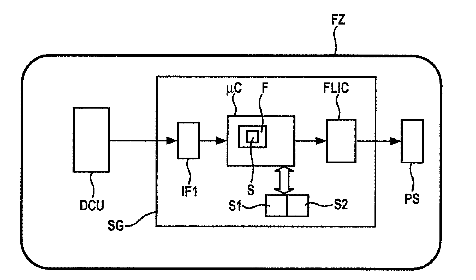
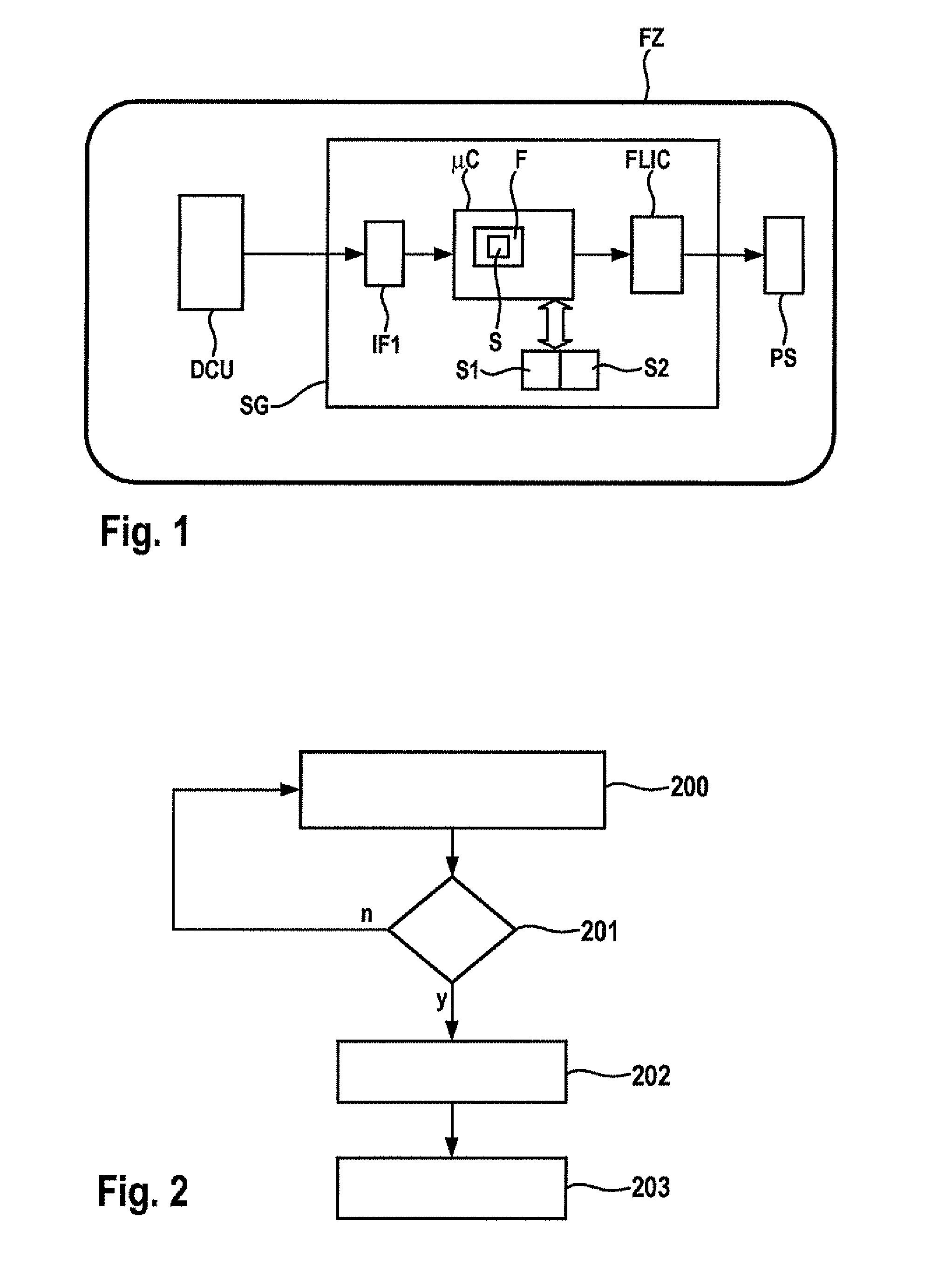
[0024]FIG. 1 shows in a block diagram control device SG in accordance with the present invention having connected components DCU and PS in a vehicle FZ. A sensor control device DCU transmits sensor signals digitally via a two-wire line to control device SG. Sensor control device DCU houses a plurality of sensors that provide accident-relevant signals. Such sensors are acceleration sensors in different spatial directions, rotary motion sensors, structure-borne noise sensors, or other conventional sensors.

[0025]These signals from sensor control device DCU are received by an interface IF1 in control device SG. In the case at hand, the interface is designed as an integrated circuit and at least reformats the sensor signals into a transmission format that is used inside of control device SG, for example, that of the SPS (serial peripheral interface) bus. The sensor signals are accordingly transmitted from interface IF1, which alternatively may also be part of a so-called system ASIC, to ...


PUM


Abstract

A method for error handling for a control device for a passenger protection system and a corresponding control device are provided, the error handling being implemented by switching off at least one function of the control device as a function of an error detection. The switching off takes place immediately after the error detection, the error qualification taking place after the switching off.

Description

FIELD OF THE INVENTION[0001]The present invention relates to a method for error handling for a control device for a passenger protection system and such a control device for a passenger protection system.BACKGROUND INFORMATION[0002]A method and a device for error storage in a control device of a motor vehicle is described in German Patent No. DE 40 40 927 C2. In this context, an error sequence memory is used, in which the error information is stored in the sequence in which previously labeled errors occurred. Additionally, in an error registration memory, for each error previously labeled there, the setting of an error labeling flag indicates whether the error exists at the moment, a respective error labeling flag being set if the error associated with it occurs, and the flag being reset as soon as the error no longer exists. An entry in the error sequence memory is made only if the relevant error labeling flag is not set for an error that is occurring.SUMMARY[0003]A method in accor...

Claims


Application Information

Patent Timeline
IPC IPC(8): B60R21/01G06F7/00
CPCB60R21/0132B60R2021/01327B60R2021/01184B60R21/0136G06F7/00
Inventor WIDMAIER, JOCHENFISLAGE, MARKUS
Owner ROBERT BOSCH GMBH
Learn More