

Nitrocarburized crankshaft member and steel for nitrocarburized crankshafts
a technology of nitrocarburized crankshafts and crankshaft parts, which is applied in the direction of crankshafts, mechanical equipment, solid-state diffusion coatings, etc., can solve the problems of crankshaft damage, crankshaft member likely to bend or warp, and easy cracking, etc., to achieve superior bending correctability, increase yield strength, and high fatigue strength
- Summary
- Abstract
- Description
- Claims
- Application Information
AI Technical Summary
Benefits of technology
Problems solved by technology
Method used
Image

Examples
Embodiment Construction
[0024]The following describes in detail several embodiments of the crankshaft member and steel for crankshafts therefor according to the present invention.
[0025]First, the manufacturing method of the crankshaft member will be described with reference to FIG. 2.
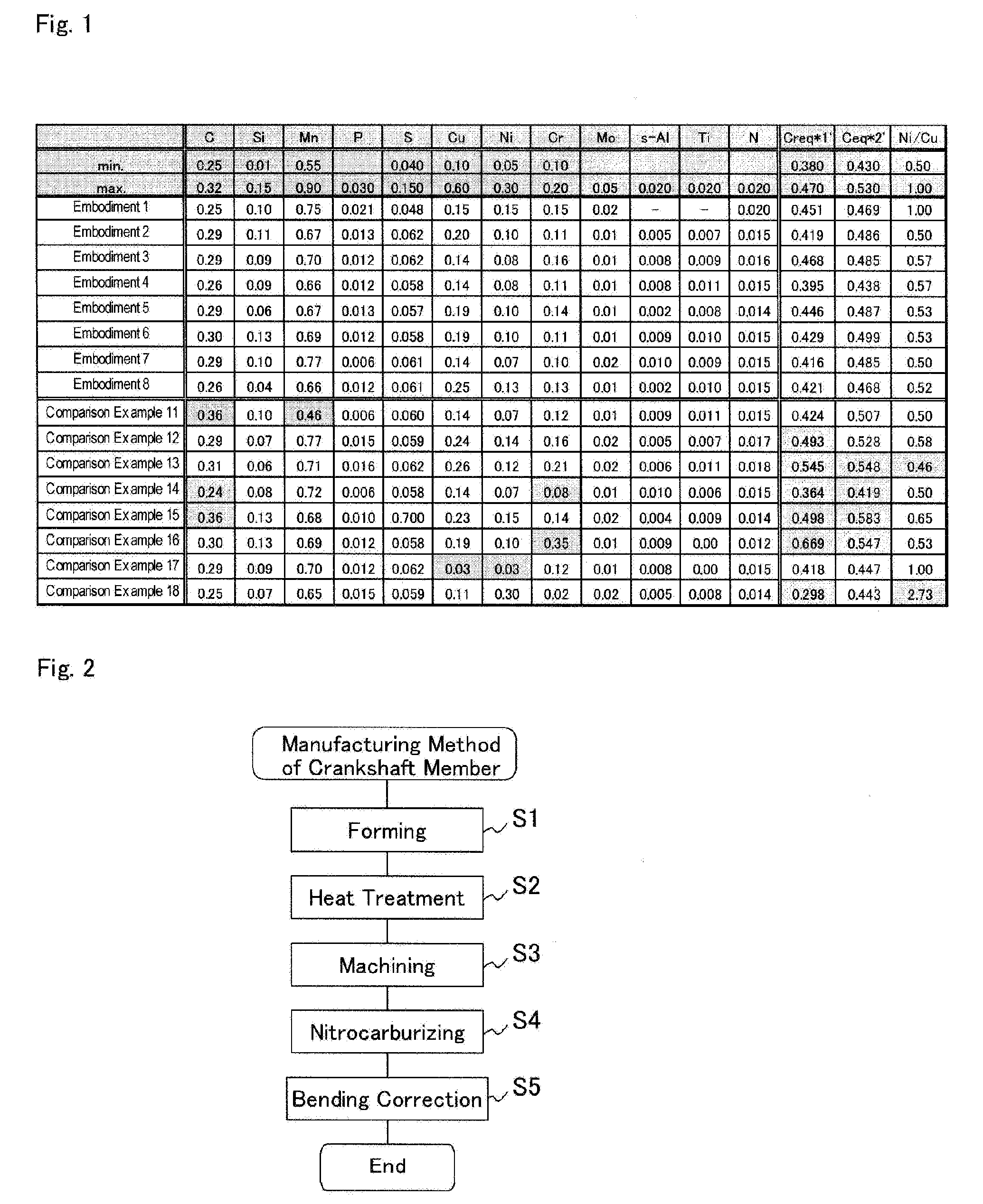
[0026]As indicated by the element compositions of FIG. 1, the steel for crankshafts of the embodiments is a medium-carbon steel that includes carbon in the relatively small amount of 0.25 to 0.32 wt %. One distinguishing characteristic of this steel is that the steel can include Cu which can exist as a trapped element in general raw material scrap as a required element.
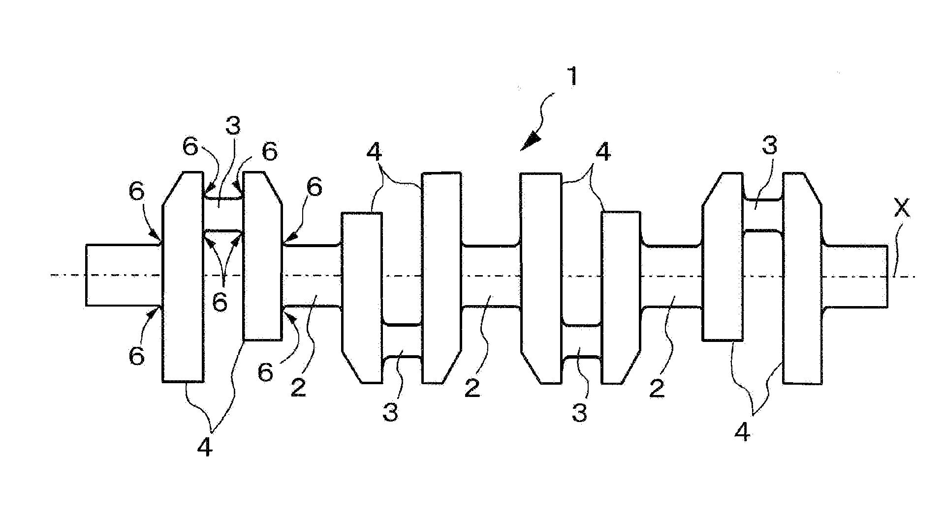
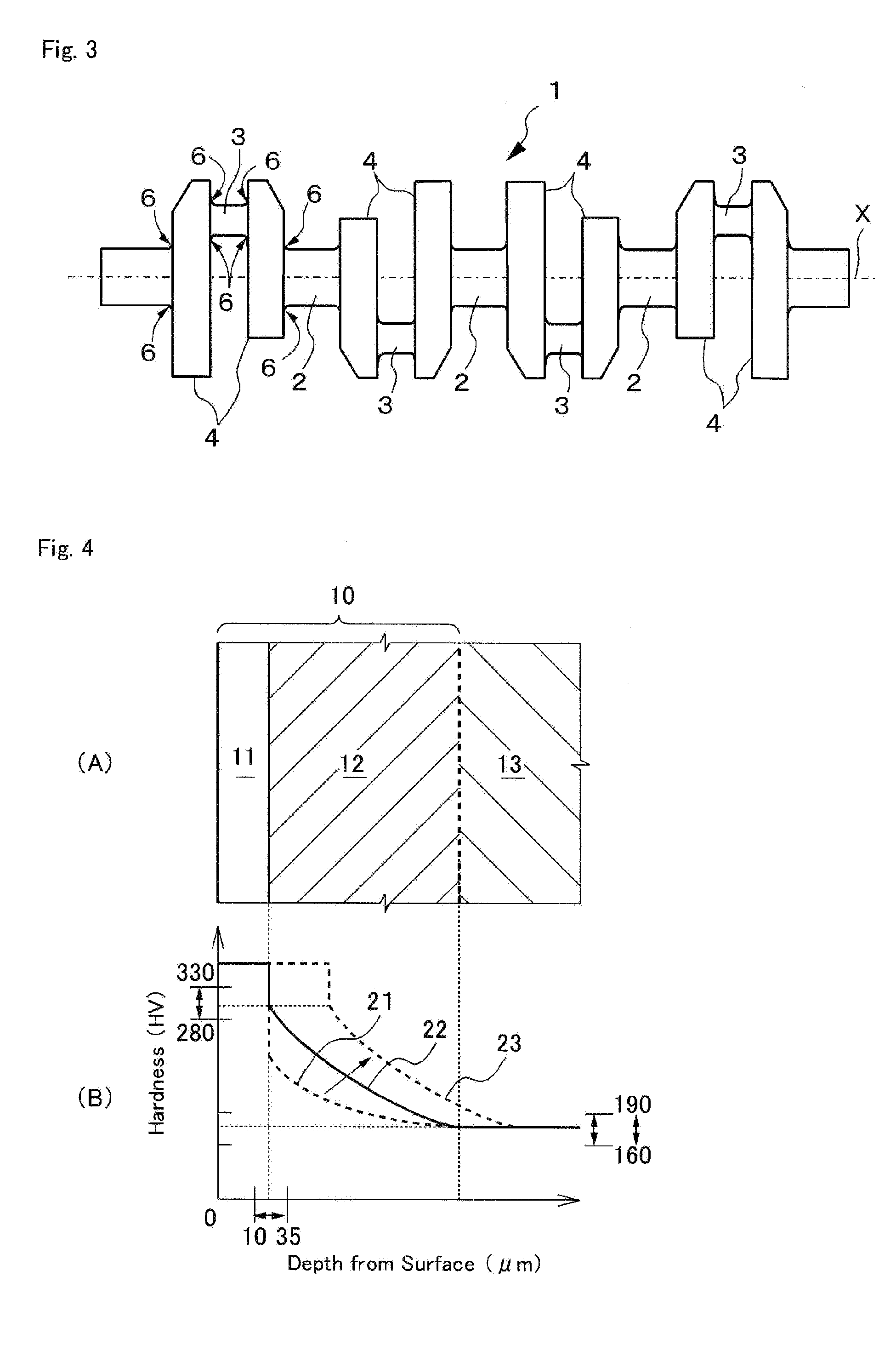
[0027]The steel for crankshafts of the embodiments that consists essentially of ferrite and perlite is achieved by subjecting the steel of the element compositions of FIG. 1 to a forming process (S1), such as hot forging, as necessary in order to bring the steel closer to the shape of the final product (refer to FIG. 3) and then implementing heat treatment (S2),...
PUM
| Property | Measurement | Unit |
|---|---|---|
| thickness | aaaaa | aaaaa |
| thickness | aaaaa | aaaaa |
| ending temperature | aaaaa | aaaaa |
Abstract
Description
Claims
Application Information