Crankshaft member and manufacturing method thereof

Active Publication Date: 2010-06-10
HONDA MOTOR CO LTD +1
View PDF1 Cites 13 Cited by
  • Summary
  • Abstract
  • Description
  • Claims
  • Application Information

AI Technical Summary

Benefits of technology

[0020]According to the invention, it is possible to achieve a crankshaft member having high fatigue strength. Further, by verifying whether or not the lamellar spacing of the perlite is within the predetermined range, it is possible to assess whether or not the fatigue strength of the product is acceptable, thereby enabling easier control of the manufacturing process a

Problems solved by technology

During the forging or the surface hardening process, the crankshaft member is likely to bend or warp.
At this time, particularly on a crankshaft member that has been subjected to a surface hardening process, such as a soft-nitriding or nitriding process, cracks readily occur on the hardened surface as a result of the bending.
These cracks may cause damage to the crankshaft.
Therefore, when the material is used for a crankshaft, the strength of the overall crankshaft member becomes inadequate.
As a result, the hardness of the har

Method used


Image

  • Crankshaft member and manufacturing method thereof
  • Crankshaft member and manufacturing method thereof
  • Crankshaft member and manufacturing method thereof

Examples


Embodiment Construction

[0034]Prior to obtaining a crankshaft disclosed in the description of the preferred embodiments of the present invention, empirical experiments such as the following were performed. The empirical experiments are described below with reference to accompanying drawings.

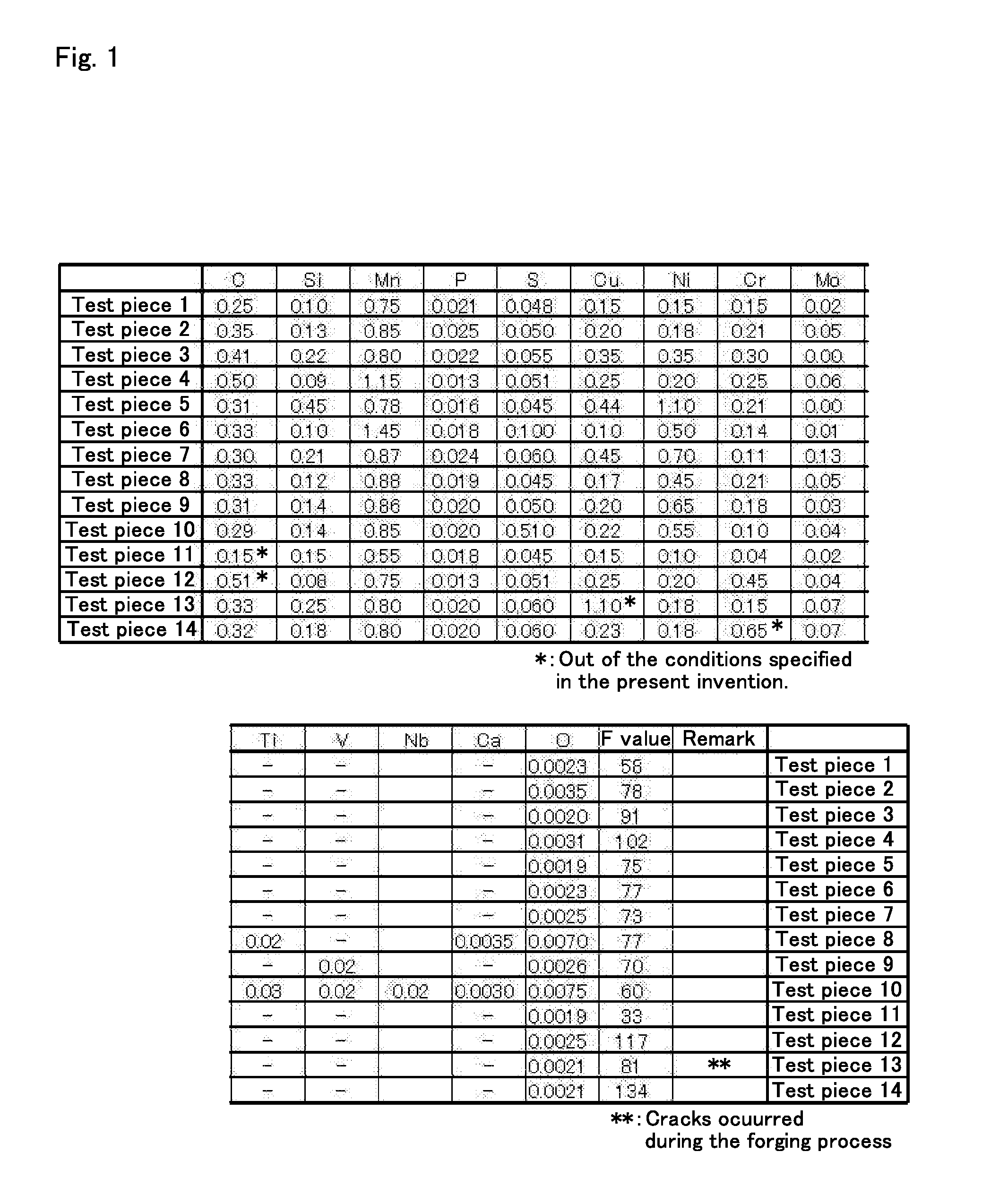
[0035]Steel comprising the components shown in FIG. 1 was melted and steel-made in a high-frequency induction furnace to obtain an ingot for test pieces 1 to 14. Each ingot was coarsely forged to a square having a cross-section of 70 square millimeters, and then hot forge to a size having a cross-section of 40 square millimeters, after reheating thereof for a period of 90 minutes at 1200 degrees Celsius. The forged square rod was then continually cooled by air blast to cool the rod, particularly the rod being cooled from 800 to 450 degrees Celsius at a cooling rate of approximately 1.0 degree Celsius per second. Additionally, from the ingot for test piece 2, a plurality of forged square rods were prepared and cooled by ...


PUM

PropertyMeasurementUnit
Temperatureaaaaaaaaaa

Abstract

The invention relates to a crankshaft member having high fatigue strength and good bending correctability, and its method of manufacture. The steel made crankshaft member mainly consists of a two-phase structure of ferrite and perlite. The steel includes C, Ni, Mn, and Cr as required elements and Si, Cu, Mo, Ti, V, Nb, Ca, and S as optional elements that may be included, in the amounts of C within the range of 0.20 to 0.50 wt %, Si within the range of 0 to 0.6 wt %, Mn within the range of 0.5 to 1.5 wt %, Cu within the range of 0 to 0.7 wt %, Ni within the range of 0.05 to 1.5 wt %, Cr within the range of 0.05 to 0.45 wt %, and Mo within the range of 0 to 0.5 wt % to satisfy the condition 115≧70 C+8 Si+23 Mn+11 Cu+128 Cr+83 Mo≧50. A portion of the member surface is provided at least with a hard nitride layer having an average hardness within the range of 300 to 450 HV. Lamellar spacing of the perlite is 0.3 μm or less.

Description

BACKGROUND OF THE INVENTION[0001]1. Field of the Invention[0002]The present invention relates to a crankshaft member and manufacturing method thereof, and more particularly to a crankshaft member having high fatigue strength and its method of manufacture.[0003]2. Description of the Background Art[0004]In a reciprocating engine of an automobile or the like, a crankshaft is used to convert the up-and-down motion of a piston into a rotating motion. The crankshaft comprises a journal portion that rotates around a rotating shaft, an arm portion provided at a predetermined interval along the rotating shaft and formed protruding sideways, and a pin portion of the protruding end portion of the arm portion that is connected via a pin to a connecting rod that connects with a piston. The up-and-down motion of the piston rotates the arm portion around the rotating shaft via the connecting rod, and is converted into a rotating motion. The rotating motion can then be extracted from the journal po...

Claims


Application Information

Patent Timeline
IPC IPC(8): F16C3/06B21K1/08
CPCB21K1/08F16C3/06Y10T74/2173Y10T29/49286C23C8/32
Inventor SAITO, ISAMUTAKITANI, YOSHIHIROKATO, SHINICHIROHOBO, MAKOTOKAMIYA, KEIICHIROMIYAZAKI, TAKAHIROKANO, TAKASHI
Owner HONDA MOTOR CO LTD
Why Eureka
Try Eureka