

Wind power generator
a generator and wind power technology, applied in the direction of machines/engines, mechanical energy handling, mechanical equipment, etc., can solve problems such as durability, and achieve the effect of enhancing the cooling efficiency of air in the nacell
- Summary
- Abstract
- Description
- Claims
- Application Information
AI Technical Summary
Benefits of technology
Problems solved by technology
Method used
Image

Examples
first embodiment
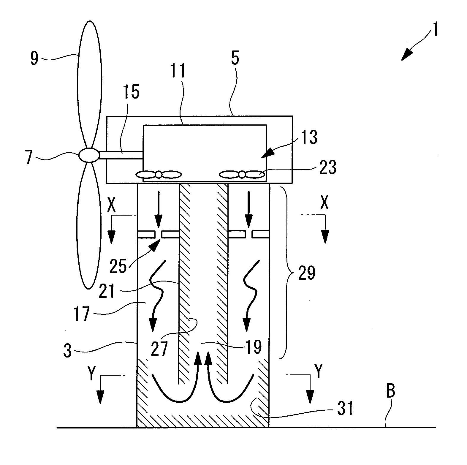
[0042]A terrestrial wind power generator 1 according to a first embodiment of the present invention will be described below with reference to FIGS. 1 to 3.
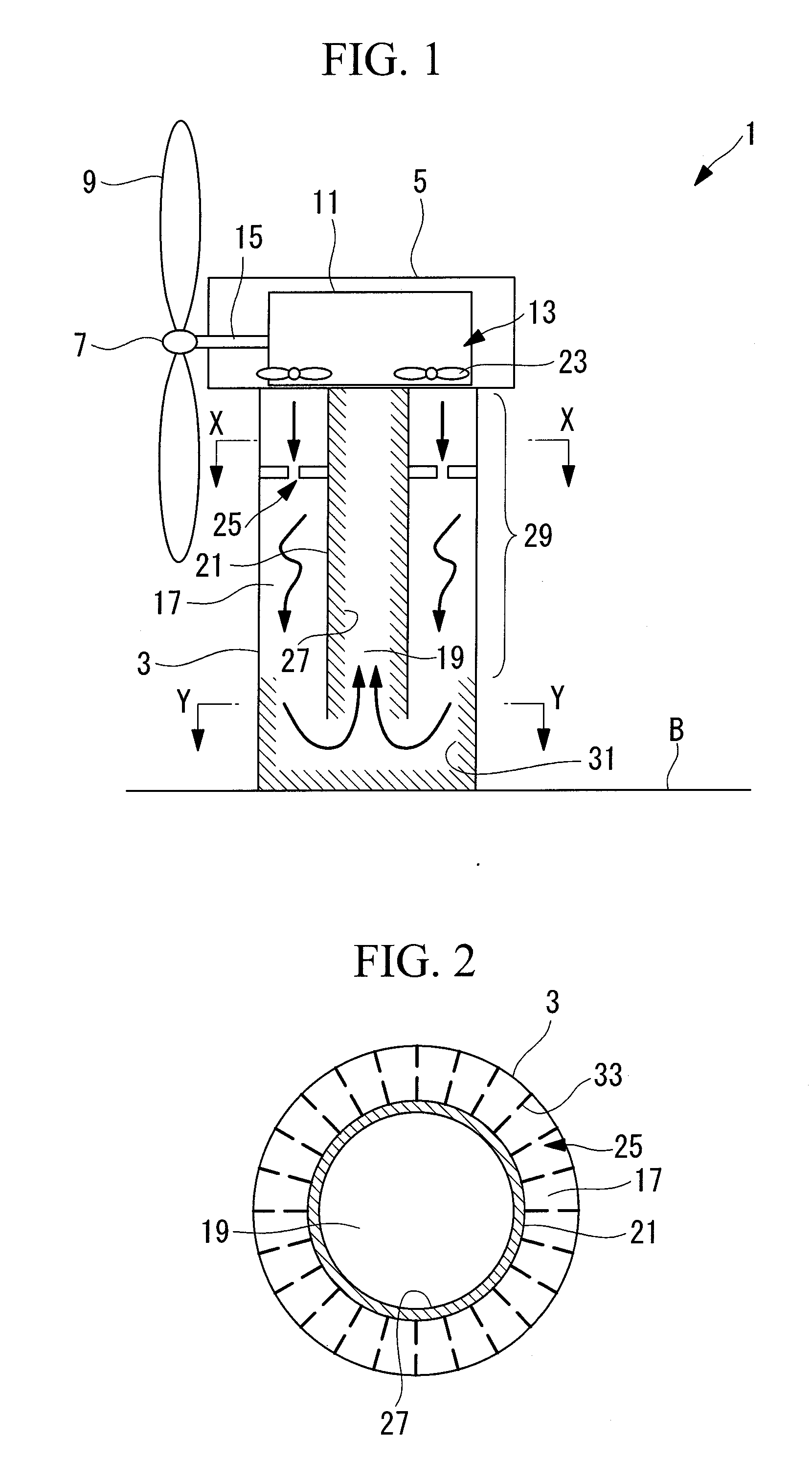
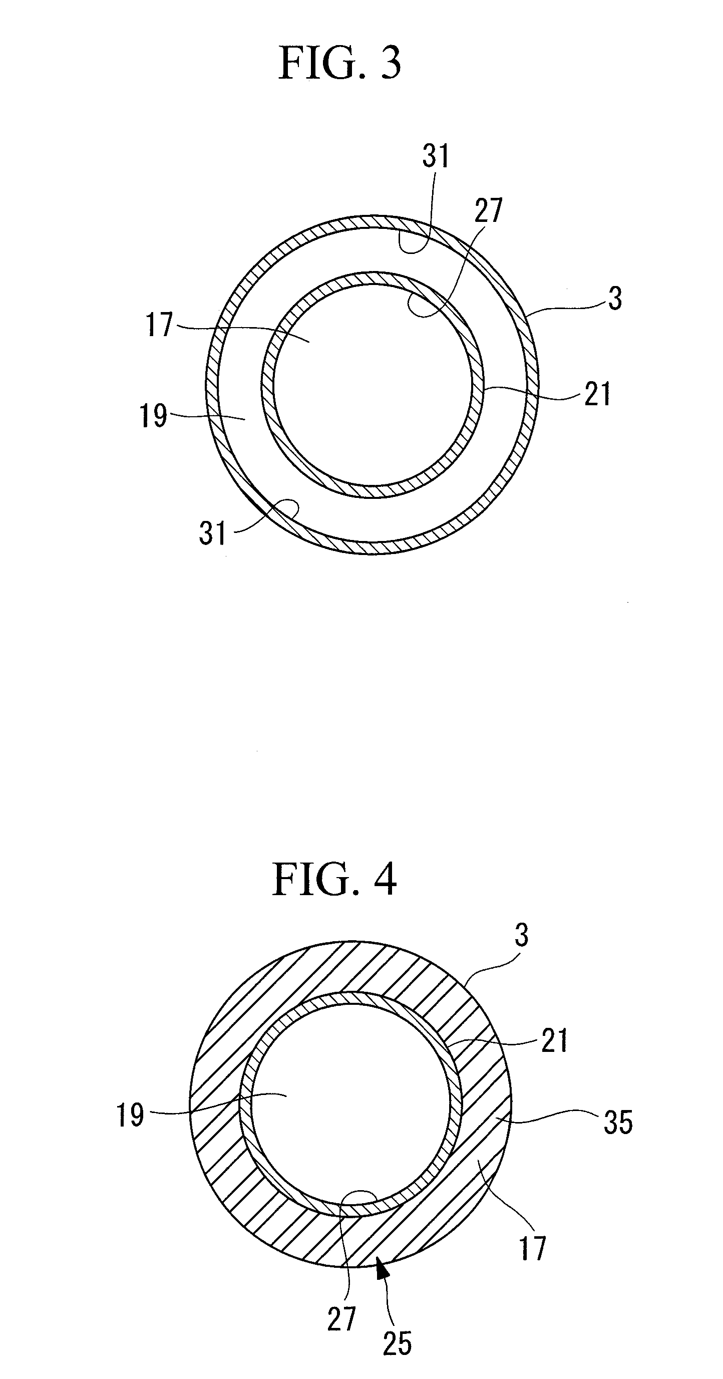
[0043]FIG. 1 is a longitudinal sectional view illustrating the schematic configuration of the wind power generator 1 according to the first embodiment. FIG. 2 is a cross-sectional view taken along line X-X in FIG. 1. FIG. 3 is a cross-sectional view taken along line Y-Y in FIG. 1.
[0044]The wind power generator 1 is provided with a tower (tower portion) 3 that is vertically erected on a base B, a nacelle 5 mounted on the upper end of the tower 3, a rotor head 7 mounted on the nacelle 5 so as to be rotatable about the substantially horizontal rotation axis thereof, a plurality of wind turbine blades 9 mounted in a radiating pattern on the rotor head 7, generator equipment 11 that generates electricity by the rotation of the rotor head 7, and cooling equipment 13.
[0045]The tower 3 is a column made of metal, concrete, or a metal-concr...
first modification
[0090]The wind power generator 1 according to a first modification will be described using FIGS. 6 and 7. FIG. 6 is a cross-sectional view of the upper portion of the tower 3, as in FIG. 2 of the first embodiment. FIG. 7 is a cross-sectional view of the lower portion of the tower 3, as in FIG. 3 of the first embodiment.
[0091]Since this modification differs from the first embodiment in the configuration of the downward passage 17 and the upward passage 19, the difference will be mainly described here.
[0092]In this modification, a hollow, substantially cylindrical tube 39 is disposed in contact with the tower 3, with its axial center being substantially parallel to the axial center of the tower 3. The tube 39 is mounted so as to extend vertically such that the open upper surface faces the nacelle 5 and the closed lower surface is in the vicinity of the lower end of the tower 3. The diameter of the tube 39 is set to substantially 45% of the diameter of the tower 3.
[0093]The tube 39 is ...
second modification
[0102]The wind power generator 1 according to a second modification will be described using FIGS. 9 and 10. FIG. 9 is a cross-sectional view of the upper portion of the tower 3, as in FIG. 2 of the first embodiment. FIG. 10 is a cross-sectional view of the lower portion of the tower 3, as in FIG. 3 of the first embodiment.
[0103]Since this modification differs from the first embodiment in the configuration of the downward passage 17 and the upward passage 19, the difference will be mainly described here.
[0104]In this modification, a pair of hollow, substantially cylindrical tubes 47 and 49 are disposed at substantially symmetric positions about the axial center of the tower 3 in such a manner that the axial centers of the tubes 47 and 49 are substantially parallel to the axial center of the tower 3 and the tube 47 is in contact with the tower 3.
[0105]The tubes 47 and 49 are mounted so as to extend vertically in such a manner that the individual open upper surfaces face the nacelle 5 ...
PUM
 Abstract
Description
Claims
Application Information