LED driving circuit having error detection function

a technology of error detection and driving circuit, which is applied in the direction of electric variable regulation, process and machine control, instruments, etc., can solve the problems of signal distortion, poor image quality, and increase the manufacturing cost of a pcb board

Inactive Publication Date: 2011-06-09
SAMSUNG ELECTRO MECHANICS CO LTD
View PDF2 Cites 16 Cited by
  • Summary
  • Abstract
  • Description
  • Claims
  • Application Information

AI Technical Summary

Benefits of technology

[0022]An aspect of the present invention provides an LED driving circuit having an error

Problems solved by technology

A method of driving this backlight unit causes motion blur due to an after image when one screen is converted into another screen, which leads to poor image quality.
However, this driving method requires the number of lines to be as many as the number of channels to be driven, which increases the man

Method used


Image

  • LED driving circuit having error detection function
  • LED driving circuit having error detection function
  • LED driving circuit having error detection function

Examples


Embodiment Construction

[0033]Exemplary embodiments of the present invention will now be described in detail with reference to the accompanying drawings.

[0034]The invention may, however, be embodied in many different forms and should not be construed as being limited to the embodiments set forth herein. Rather, these embodiments are provided so that this disclosure will be thorough and complete, and will fully convey the scope of the invention to those skilled in the art. In the drawings, the same reference numerals will be used throughout to designate the components having substantially the same configuration and function.

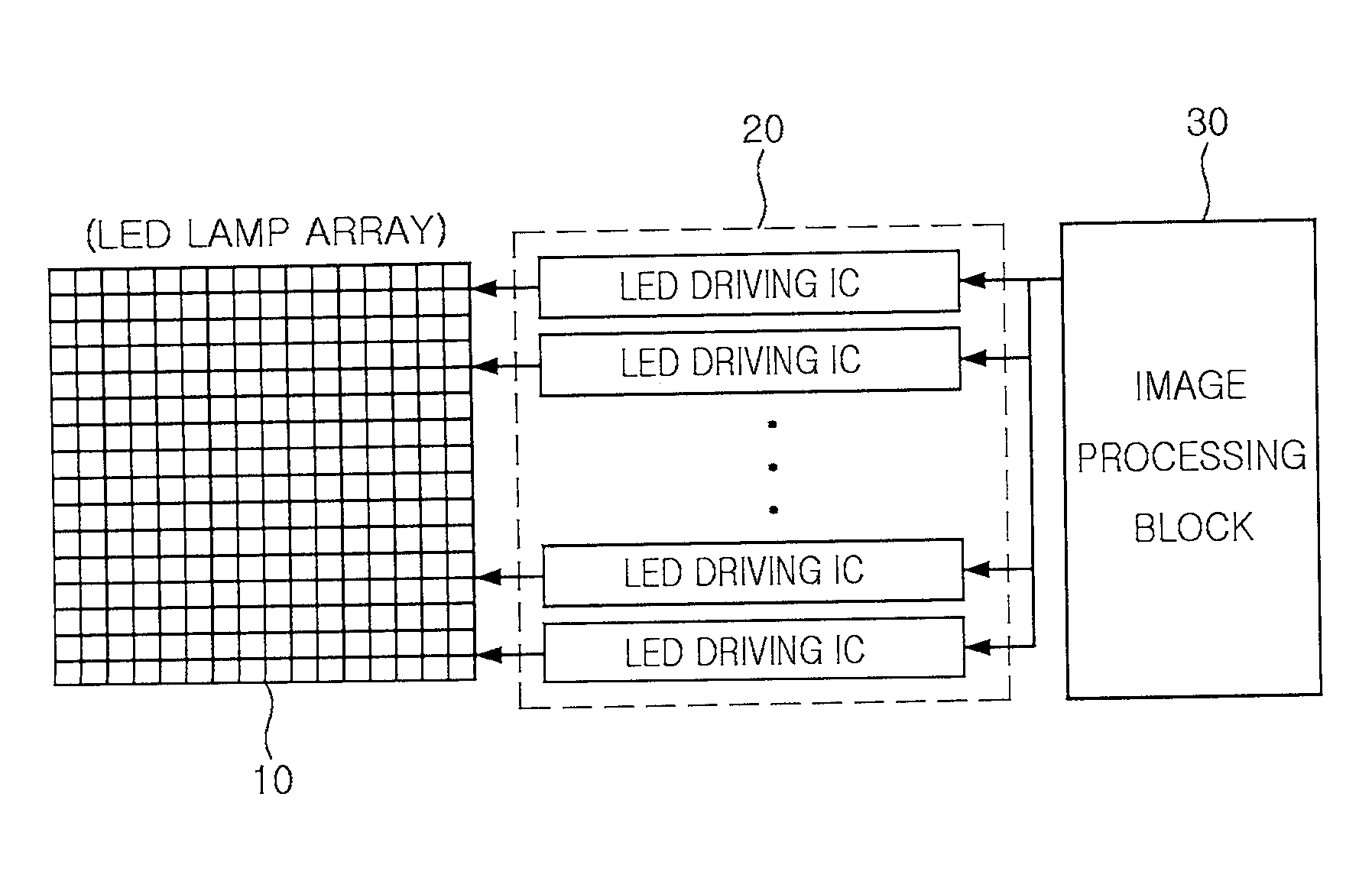
[0035]FIG. 3 is a block diagram illustrating an LED driving circuit according to an exemplary embodiment of the invention. Referring to FIG. 3, an LED driving circuit according to this embodiment may include a shift register 200, a scan register 300, a first error detection unit 500, a second error detection unit 600, and a logic operation unit 700. The shift register 200 separates dimmi...


PUM


Abstract

There is provided an LED driving circuit. An LED driving circuit according to an aspect of the invention may include: a shift register separating dimming data and control data from serial peripheral interface (SPI) data and outputting the dimming data and the control data in predetermine data units; a scan register generating scan data according to the control data from the shift register; a first error detection unit detecting an error in the dimming data from the shift register; a second error detection unit detecting an error in the scan data from the scan register; and a logic operation unit performing an OR operation on an output signal from the first error detection unit and an output signal from the second error detection unit.

Description

CROSS-REFERENCE TO RELATED APPLICATIONS[0001]This application claims the priority of Korean Patent Application No. 10-2009-0121835 filed on Dec. 9, 2009, in the Korean Intellectual Property Office, the disclosure of which is incorporated herein by reference.BACKGROUND OF THE INVENTION[0002]1. Field of the Invention[0003]The present invention relates to an LED driving circuit having an error detection function that is applicable to an LED TV set using an LED backlight unit, and more particularly, to an LED driving circuit having an error detection function that can detect errors caused by noise such as a surge or electrostatic discharge.[0004]2. Description of the Related Art[0005]In general, liquid crystal displays (LCDs) are light receiving elements that cannot emit light by themselves, and thus necessarily require backlight units (BLUs) in order to display a screen.[0006]Cold cathode fluorescent lamps (CCFLs) and external electrode fluorescent lamps (EEFLs) have been used as the l...

Claims


Application Information

Patent Timeline
IPC IPC(8): H05B37/02
CPCH05B33/0821G09G3/3426G09G2330/12G09G2320/064G09G2330/08G09G2310/024H05B45/40
Inventor RYU, JE HYUKYOUM, JUNG EUN
Owner SAMSUNG ELECTRO MECHANICS CO LTD
Why Eureka
Try Eureka