Wireless Galvanic Charging Device,Method of Operation Thereof and Mobile Electric Device to be Charged

a technology of galvanic charging and mobile electric devices, applied in the field of charging devices, can solve the problems of unnecessary energy consumption, substantial waste of energy, short circuit,

Inactive Publication Date: 2011-06-09
NOKIA CORP
View PDF13 Cites 268 Cited by
  • Summary
  • Abstract
  • Description
  • Claims
  • Application Information

AI Technical Summary

Benefits of technology

[0008]By providing a charging device that is waiting for a wireless signal from the mobile device to be charged unnecessary activation of the electrodes can be avoided and thus unnecessary energy consumption can be avoided.
[0009]Preferably, controller is configured to depower the electrodes as a default to even further reduce the energy consumption of the charging device.
[0010]The controller may be configured to determine on the basis of the wireless signal if the mobile device is of a type that can be charged with the charging device. Thus, any incompatible mobile devices will not be inadvertently charged in incorrect manner.
[0026]Preferably, the current to the positive contact electrodes that have been identified as being part of a short circuit is reduced.

Problems solved by technology

Various problems are associated with these types of charging devices.
One of the problems is that the electrodes are always powered when the charging device is on, which leads to unnecessary energy consumption.
Given the enormous amount of charging devices that are in use on the whole planet this constitutes a substantial waste of energy.
Another of the problem is that conventional charges require an exact placement or alignment of the galvanic contacts on the device to be charged with the galvanic contacts of the charging device.
However, short circuiting problems and incompatibility issues are associated with this type of charging devices.

Method used


Image

  • Wireless Galvanic Charging Device,Method of Operation Thereof and Mobile Electric Device to be Charged
  • Wireless Galvanic Charging Device,Method of Operation Thereof and Mobile Electric Device to be Charged
  • Wireless Galvanic Charging Device,Method of Operation Thereof and Mobile Electric Device to be Charged

Examples


Embodiment Construction

[0037]In the following detailed description, the charging device according to the invention will be described by the preferred embodiments. The mobile device containing a battery to be charged will also be described.

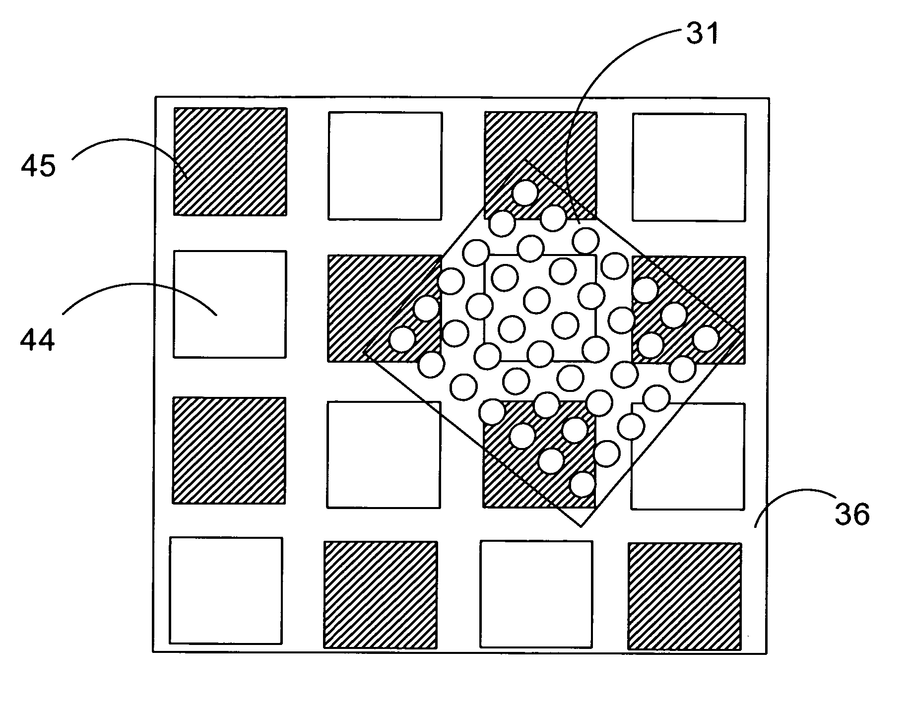
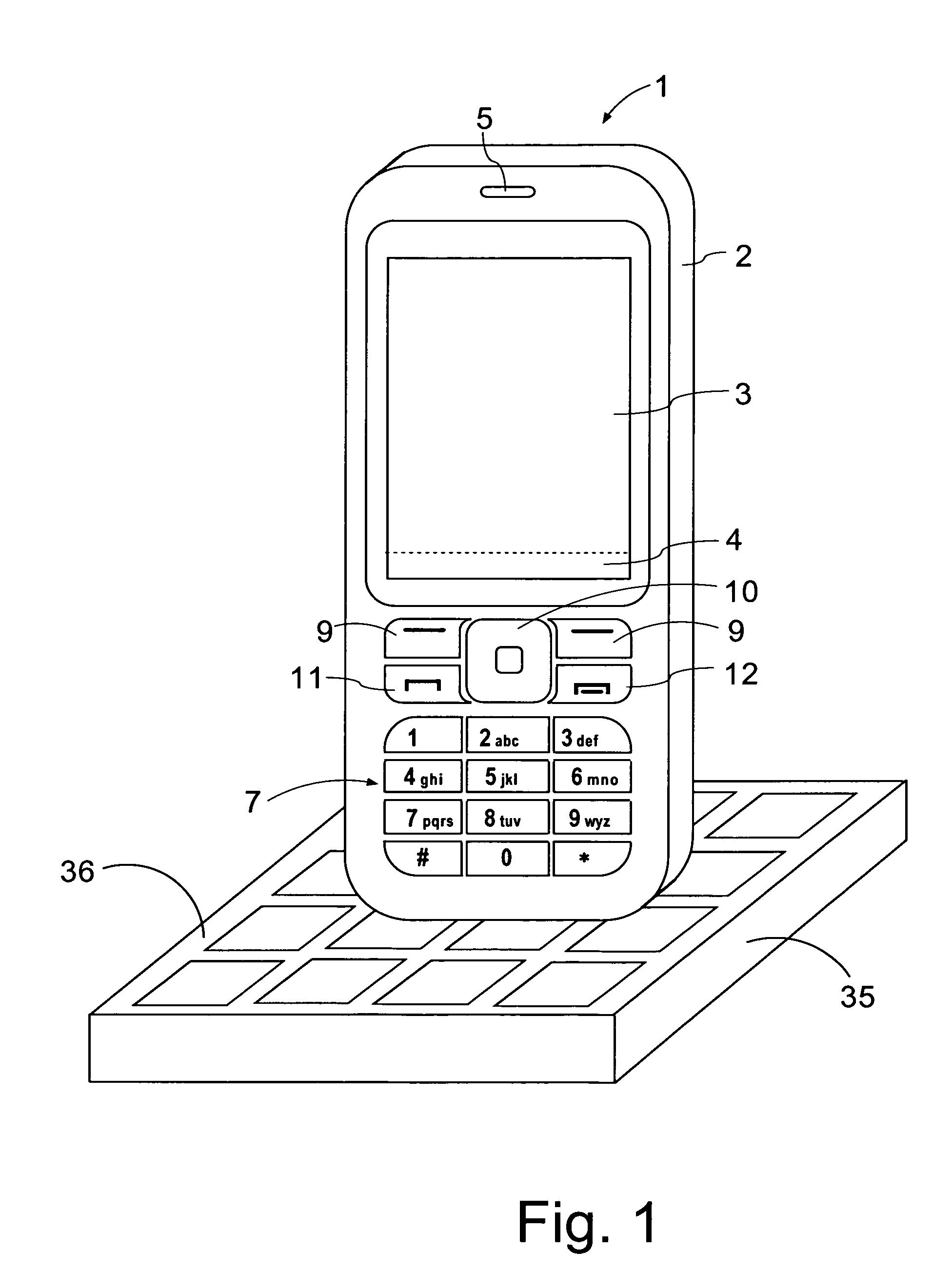
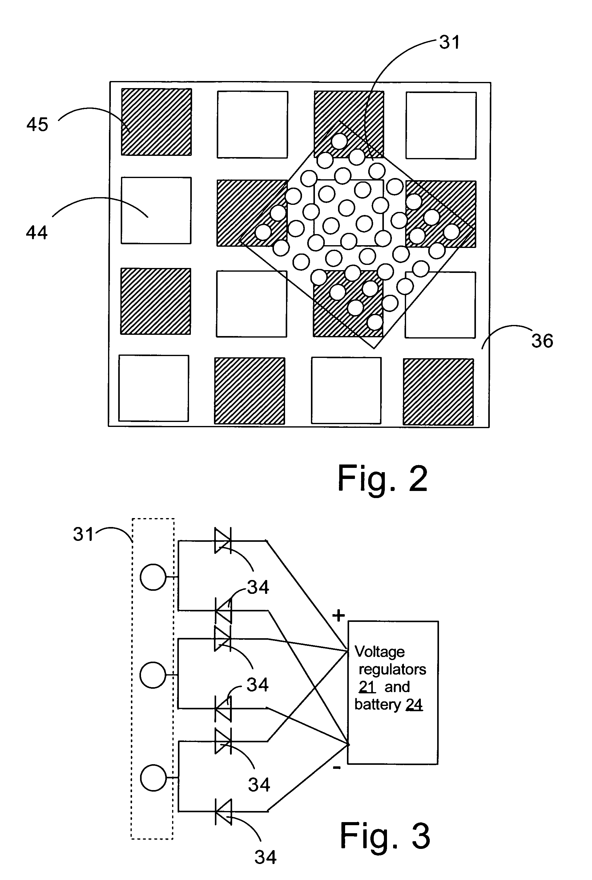
[0038]FIG. 1 illustrates a charging device 35 in the form of a charging pad. The charging device 35 has a housing that is provided with a charging pad 36 of its top surface. The charging pad is provided with a matrix of positive and negative electrodes. The charging device 35 can be connected to a mains socket 50 (A / C, typically 110 or 240 V) by a cable and plug (not shown).

[0039]The mobile phone 1 comprises a user interface having a housing 2, a display 3, an on / off button (not shown), a speaker 5 (only the opening is shown), and a microphone 6 (not visible in FIG. 1). The phone 1 according to the first preferred embodiment is adapted for communication via a cellular network, such as the GSM 900 / 1800 MHz network, but could just as well be adapted for use with a Code Div...


PUM


Abstract

A wireless charging device (35) for charging a battery of a mobile electronic device (1). The charging device (35) includes a wireless receiver (39) and a plurality of electrodes (44, 45) that are connected to a power source. The power source is controlled by a controller (40) that is coupled to the wireless receiver (39). Whilst the wireless receiver (39) receives a wireless signal that is associated with a compatible mobile device (1) the controller (40) instructs the power source to power the electrodes (44, 45). Alternatively, the wireless signal can be indicative of the need of the mobile device (1) to be charged and the controller (40) will only power the electrodes (44, 45) if a signal indicating that the mobile device (1) needs to be charged is received. A mobile battery operated device (1) that sends an indicating signal when the battery of the device needs to be charged.

Description

FIELD OF THE INVENTION[0001]The present invention relates to charging devices for mobile battery operated devices, in particular to charging devices for wireless charging of a battery in an external mobile device. Further, the invention relates to a method of charging a battery in a mobile electronic device.BACKGROUND OF THE INVENTION[0002]Conventional charging devices are provided with a cradle with galvanic contacts or with a wired connector with galvanic contacts to create electrical contact with a mobile device to be charged. Various problems are associated with these types of charging devices.[0003]One of the problems is that the electrodes are always powered when the charging device is on, which leads to unnecessary energy consumption. Given the enormous amount of charging devices that are in use on the whole planet this constitutes a substantial waste of energy.[0004]Another of the problem is that conventional charges require an exact placement or alignment of the galvanic co...

Claims


Application Information

Patent Timeline
Patent Type & Authority Applications(United States)
IPC IPC(8): H02J7/00
CPCH02J7/025H02J7/0004H02J7/00036H02J7/00047H02J50/40H02J50/05H02J50/90
Inventor HAUTANEN, JUKKA OLAVI
Owner NOKIA CORP
Why Eureka
Try Eureka