Inkjet head

a technology of inkjet head and inkjet cartridge, which is applied in the direction of printing, inking apparatus, etc., can solve the problems of deteriorating the characteristics of inkjet head, and achieve the effect of preventing oxidization and preventing short circui

Inactive Publication Date: 2011-06-09
SAMSUNG ELECTRO MECHANICS CO LTD
View PDF2 Cites 11 Cited by
  • Summary
  • Abstract
  • Description
  • Claims
  • Application Information

AI Technical Summary

Benefits of technology

[0011]An aspect of the present invention provides an inkjet head capable of preventing the oxidization of an upper electrode of

Problems solved by technology

Such materials forming the upper electrode are oxidized by most of the chemicals such as acid, alka

Method used


Image

  • Inkjet head
  • Inkjet head
  • Inkjet head

Examples


Embodiment Construction

[0027]Exemplary embodiments of the present invention will now be described in detail with reference to the accompanying drawings. The invention may, however, be embodied in many different forms and should not be construed as being limited to the embodiments set forth herein. Rather, these embodiments are provided so that this disclosure will be thorough and complete, and will fully convey the scope of the invention to those skilled in the art.

[0028]Throughout the drawings, the same reference numerals will be used to refer to the same or like parts.

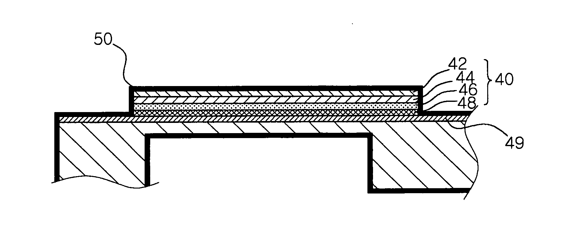
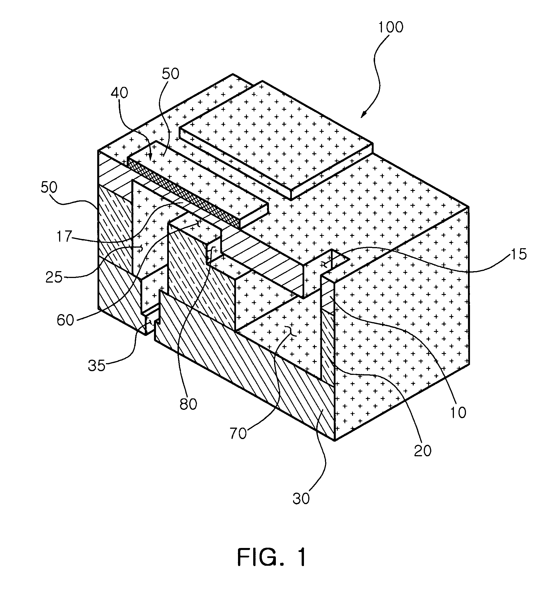
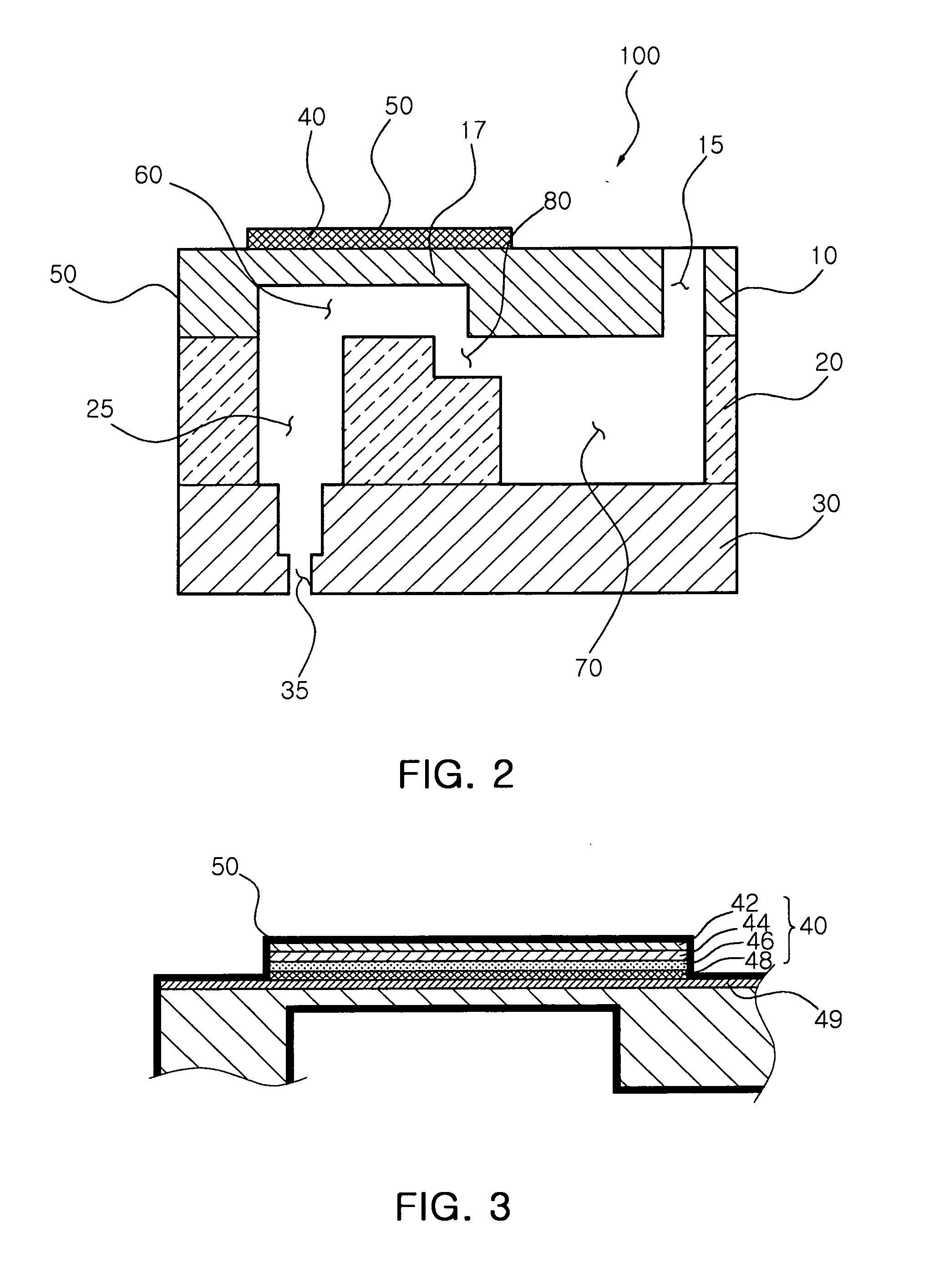
[0029]FIG. 1 is a schematic cutaway perspective view illustrating an inkjet head according to an exemplary embodiment of the present invention. FIG. 2 is a schematic cross-sectional view illustrating an inkjet head according to an exemplary embodiment of the present invention. FIG. 3 is a schematic cross-sectional view illustrating a piezoelectric actuator in the inkjet head of FIG. 2.

[0030]Referring to FIGS. 1 through 3, an inkjet head 10...


PUM


Abstract

There is provided an inkjet head including: a flow path plate having a plurality of ink chambers; a nozzle plate having a plurality of nozzles connected to the respective ink chambers in order to eject ink in the ink chambers to the outside; a piezoelectric actuator provided above the ink chambers and controlling pressure of the ink chambers; and a parylene protective film provided in order to prevent oxidization of the piezoelectric actuator.

Description

CROSS-REFERENCE TO RELATED APPLICATIONS[0001]This application claims the priority of Korean Patent Application No. 10-2009-0119609 filed on Dec. 4, 2009, in the Korean Intellectual Property Office, the disclosure of which is incorporated herein by reference.BACKGROUND OF THE INVENTION[0002]1. Field of the Invention[0003]The present invention relates to an inkjet head, and more particularly, to an inkjet head including a parylene protective film which prevents an upper electrode of a piezoelectric actuator from being oxidized.[0004]2. Description of the Related Art[0005]An inkjet head generally converts electrical signals into physical impulses so that ink droplets are ejected through small nozzles.[0006]In recent years, a piezoelectric inkjet head has been used in industrial inkjet printers. For example, the piezoelectric inkjet head is used to directly form a circuit pattern by spraying ink prepared by melting metals such as gold and silver onto a printed circuit board (PCB). The p...

Claims


Application Information

Patent Timeline
IPC IPC(8): B41J2/045
CPCB41J2/14233B41J2/14B41J2/17553B41J2/14129B41J2202/03
Inventor KIM, JAE HUNKANG, YUN SUNGYOU, MIN YOUNGYANG, JU HWAN
Owner SAMSUNG ELECTRO MECHANICS CO LTD
Why Eureka
Try Eureka