Electronic microscope

Inactive Publication Date: 2011-06-09
OMEGA VISION
View PDF3 Cites 36 Cited by
  • Summary
  • Abstract
  • Description
  • Claims
  • Application Information

AI Technical Summary

Benefits of technology

[0042]The outer body of the handle and the outer case of the lens controller may have a plurality of anti-slip protrusions formed on the outer circumference, in which the anti-slip protrusions prevent slipping when a user holds the handle.
[0043]According to exemplary embodiments of the present invention as set forth above, the diffusion member or diffusion plate radiates light having uniform brightness on the entire surface of the object by uniformly diffusing light emitted from the LEDs, and the first and second reflection-preventing sections scatter light reflected from the CCD or CMOS sensor after reflected from the object to be examined. This, as a result, makes it possible to produce a clear and clean image of the object, which is converted into electrical image signals, as well as to recognize a minute structure of the object to be examined so as to ensure precise observation, thereby imp

Problems solved by technology

However, the conventional electronic microscope used in the digital imaging system fails to correctly pick up an image of an object to be examined since the entire object is not uniformly illuminated by the light that is emitted from the LED, because it is propagated directly on the object.
As a result, the superimposed images disadvantageously degrade image quality to the extent that minute structures are not recognizable.
In addition, the conventional electronic microscope for the digital imaging system is not easy to use at home because, in order to adjust the magnification of the image of the object to be examined, a group of zoom lenses and a group of magnification lenses must be separately provided, or, alternatively, a light guide cap having a suitable magnification must be coupled to the electronic microscope.
In addition, the electronic microscope for the digital imaging system as described above is a very expensive and specialized product in which an image processing device and a monitor are provided together with the electronic microscope.
Thus, it is not practical for use in homes, small factories, school laboratories, or the like.
Furthermore, the conventional electronic microscope for the digital imaging system is not suitable for observing specific regions of the body, such as ears, nose, and mouth.
The conventional electronic microscope does not properly magnify specific one of acupuncture spot

Method used


Image

  • Electronic microscope
  • Electronic microscope
  • Electronic microscope

Examples


Embodiment Construction

[0066]Reference will now be made in detail to various embodiments of the present invention(s), examples of which are illustrated in the accompanying drawings and described below. Throughout this document, reference should be made to the drawings, in which the same reference numerals and signs are used throughout the different drawings to designate the same or similar components. In the following description of the present invention, detailed descriptions of known functions and components incorporated herein will be omitted when they may make the subject matter of the present invention unclear.

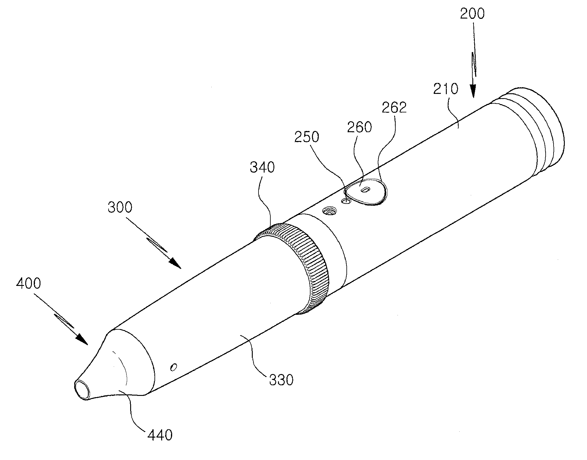
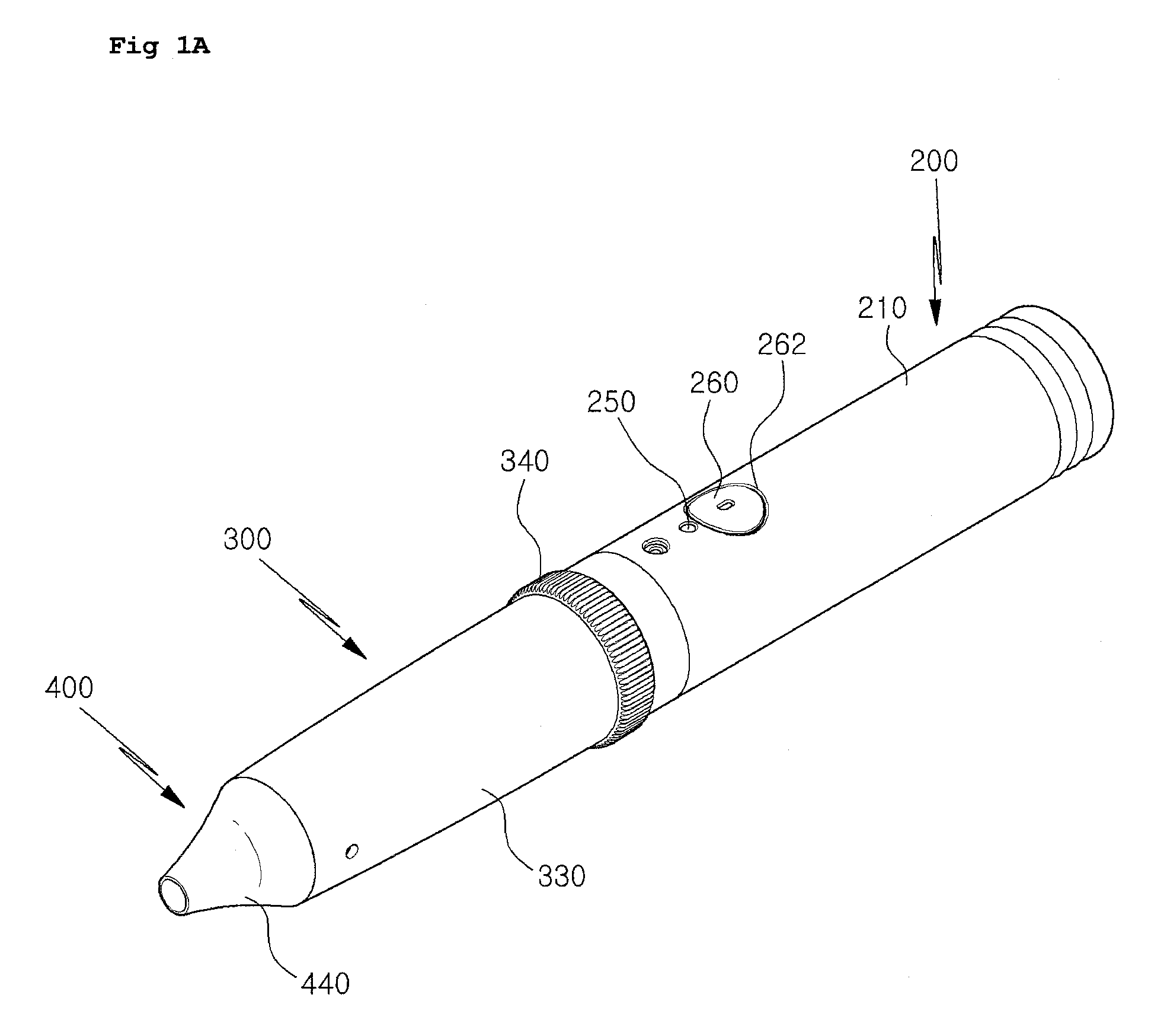
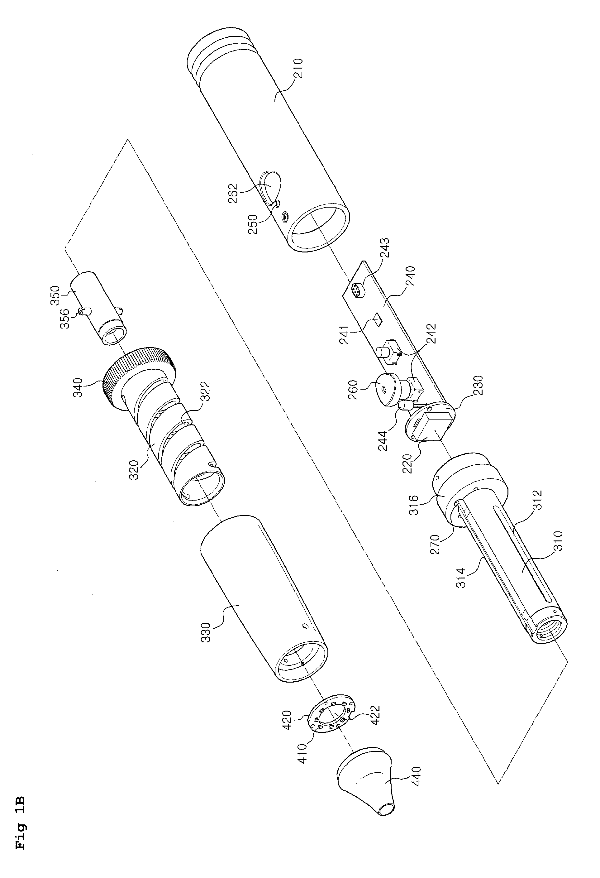
[0067]FIG. 1A is an assembled perspective view showing an electronic microscope according to a first exemplary embodiment of the invention, FIG. 1B is an exploded perspective view of FIG. 1A, FIG. 2 is a longitudinal cross-sectional view showing the internal structure of the electronic microscope according to the first exemplary embodiment of the invention, FIG. 3 is a perspective view showing ...


PUM


Abstract

An electronic microscope includes a handle having an outer body enclosing a main body and an image sensor, a lens controller fixed to the front end of the outer body of the handle, and a light guide coupled to the front end of the lens controller. The lens controller includes an inner case having a guide slot in the circumference and a flange on one end to which the handle is coupled, an outer case rotatably coupled with the inner case from outside and having a spiral passage in the circumference communicating with the guide slot, and a lens unit inserted into the inner case. The lens unit moves back and forth in response to rotation of the outer case. The light guide includes a LED board, LEDs radially mounted on the LED board, and an observation filter detachably provided on the front end of the lens controller.

Description

BACKGROUND OF THE INVENTION[0001]1. Field of the Invention[0002]The present invention relates to an electronic microscope. More particularly, the present invention relates to an electronic microscope that can pick up an image of a specific body region, such as the skin, the scalp, or the interior of the mouth, ears, or nose, and display the image by magnifying it in order to enable early diagnosis of a disease and its proper treatment, and that can be easily connected to a Personal Computer (PC) so that the magnified image of the skin or the interior of the ears can be observed at home, or so that specific body regions, such as the back or the nape of the neck, which a user cannot observe with the naked eye by him / herself, can be observed via a computer monitor.[0003]2. Description of Related Art[0004]In general, a digital imaging system includes an electronic microscope and a display device. The electronic microscope picks up an image of an object to be examined by magnifying it an...

Claims


Application Information

Patent Timeline
IPC IPC(8): H04N7/18
CPCA61B1/00105A61B1/233A61B1/24G02B21/084A61B19/5223G02B21/0008A61B1/267A61B90/20A61B1/227
Inventor KIM, CHANG HYUN
Owner OMEGA VISION
Why Eureka
Try Eureka