
Image-processing device for color image data and method for the image processing of color image data

a color image and image data technology, applied in the field of color image processing, can solve the problems of loss, inability to display raw data of such an image, inability to realize real-time display, etc., and achieve the effect of reducing artifacts, reducing costs, and realizing very easily

Inactive Publication Date: 2011-06-09
BAUMER OPTRONIC
View PDF2 Cites 13 Cited by
  • Summary
  • Abstract
  • Description
  • Claims
  • Application Information

AI Technical Summary

Benefits of technology

[0003]The raw data of such an image, however, is not displayable on standard displays. For this purpose, a conversion is generally performed wherein the signals of several pixels of the sensor are interpolated. Here there is generally the problem that such conversions can generate artifacts, such as color fringes, or are computationally intensive, so that among other things they are not suitable for real-time display. In addition, a conversion process, for example, into RGB values like those used in common image formats, is lossy. The invention is therefore based on the task of disclosing a more effective conversion of color image data that is simple enough that it can also be easily implemented as hardware and that allows true-color, low-artifact displays in real time.
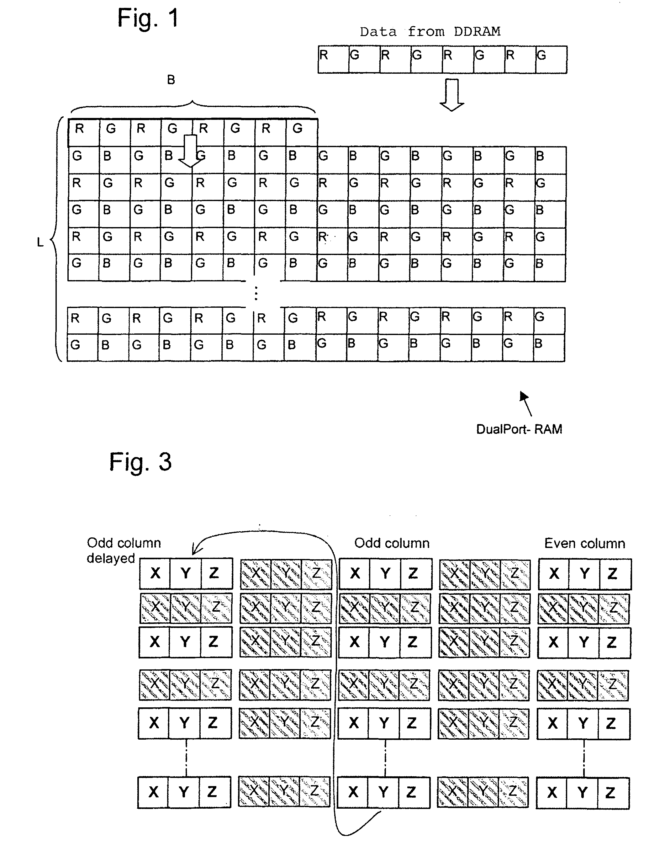
[0010]An especially effective and fast use of memory is realized, furthermore, when the image data in Bayer format is continuously written into the data buffer with a length L of at least 32 pixels, advantageously exactly 32 pixels, and a width B of at least 8 pixels, advantageously exactly 8 pixels.
[0011]In addition to the first color component it is also advantageous to calculate by means of the computational device, from the n×n matrix, a fourth color component with lower spatial resolution (YL) relative to the first color component by means of another adder network. Instead of the first color component (YH), this fourth color component can be used for calculating color correction, wherein a signal derived from the difference of the first and—advantageously weighted—fourth color component (YH−YL) is added to the corrected output signal. The two color components YH and YL here can be weighted with different multipliers in order to adapt the sizes of the two components in the difference formation to each other. Thus, in a refinement it is provided to use the difference YH−118*YL. A simple, effective sharpness filter can be realized in this way.
[0016]In a refinement of the invention, the image-processing device can be advantageously designed to normalize the color components to a white value by means of programmable gain settings and to format a first data sequence from the first color component (YH) or alternatively the fourth color component (YL), as well as the second and the third color components. This is beneficial for achieving the most authentic representation possible for the colors of the image data.
[0021]The image data stream that is output to the end device can still be advantageously DCT coded (DCT=“Discrete Cosine Transformation”) to produce an effective reduction. DCT coding can also be realized very easily through hardware components, such as digital signal processors (DSPs) or multiply-accumulate units (MACs).
[0022]Because of the mode of processing the signals according to the invention, the data buffer can comprise, in an especially preferred way, a dual-port RAM. Such memories are indeed small, but because the data is processed in a pipeline process, the image data can be written continuously from the image memory into the dual-port RAM while other image data is simultaneously read again for further processing. This is an essential element to also providing real-time conversion of the image data with reduced artifacts by means of pipeline processing.

Problems solved by technology

The raw data of such an image, however, is not displayable on standard displays.
Here there is generally the problem that such conversions can generate artifacts, such as color fringes, or are computationally intensive, so that among other things they are not suitable for real-time display.
In addition, a conversion process, for example, into RGB values like those used in common image formats, is lossy.
Large integrated SRAM areas require chip area, and are therefore disadvantageous.

Method used


Image

  • Image-processing device for color image data and method for the image processing of color image data
  • Image-processing device for color image data and method for the image processing of color image data
  • Image-processing device for color image data and method for the image processing of color image data

Examples


Embodiment Construction

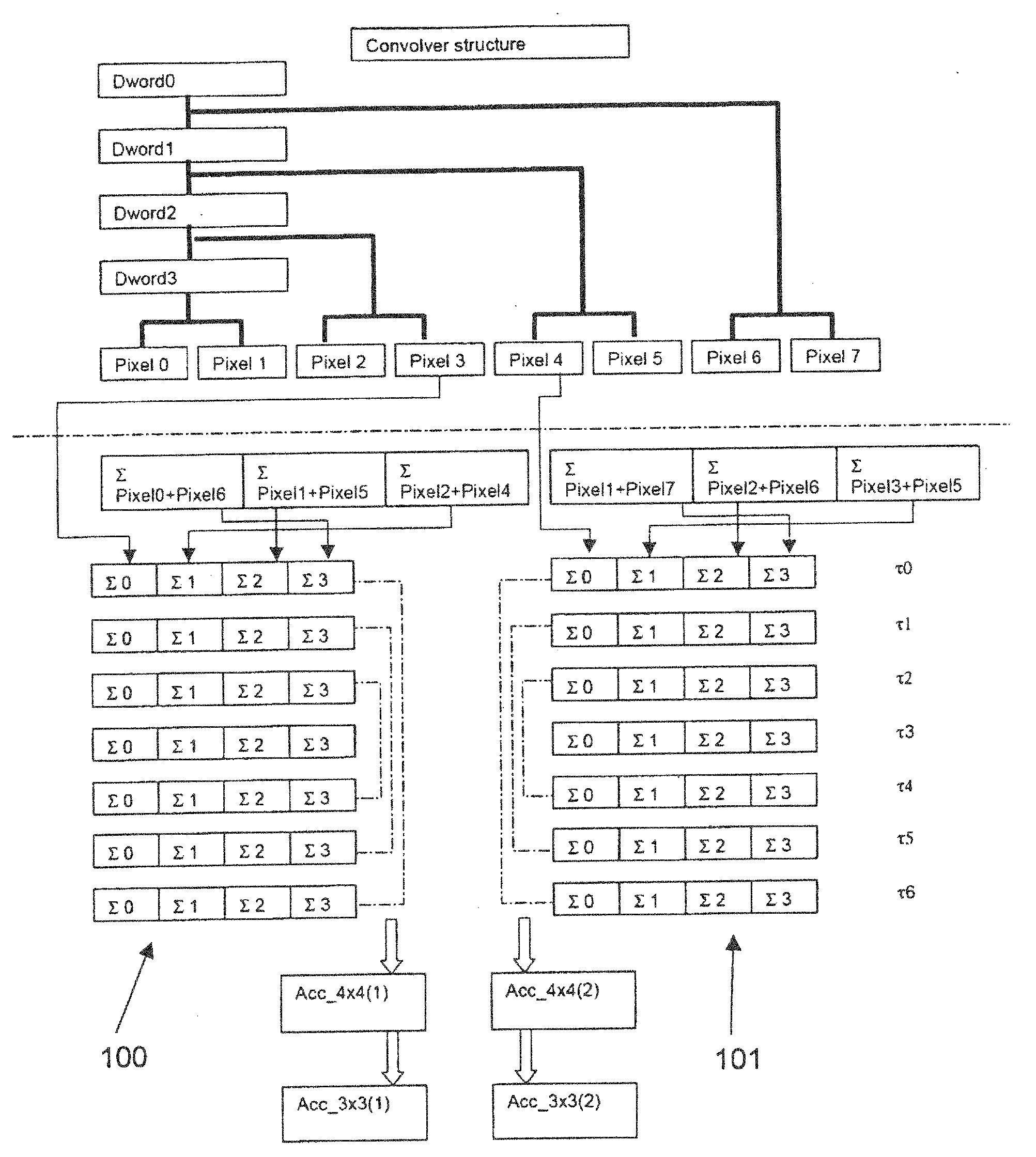
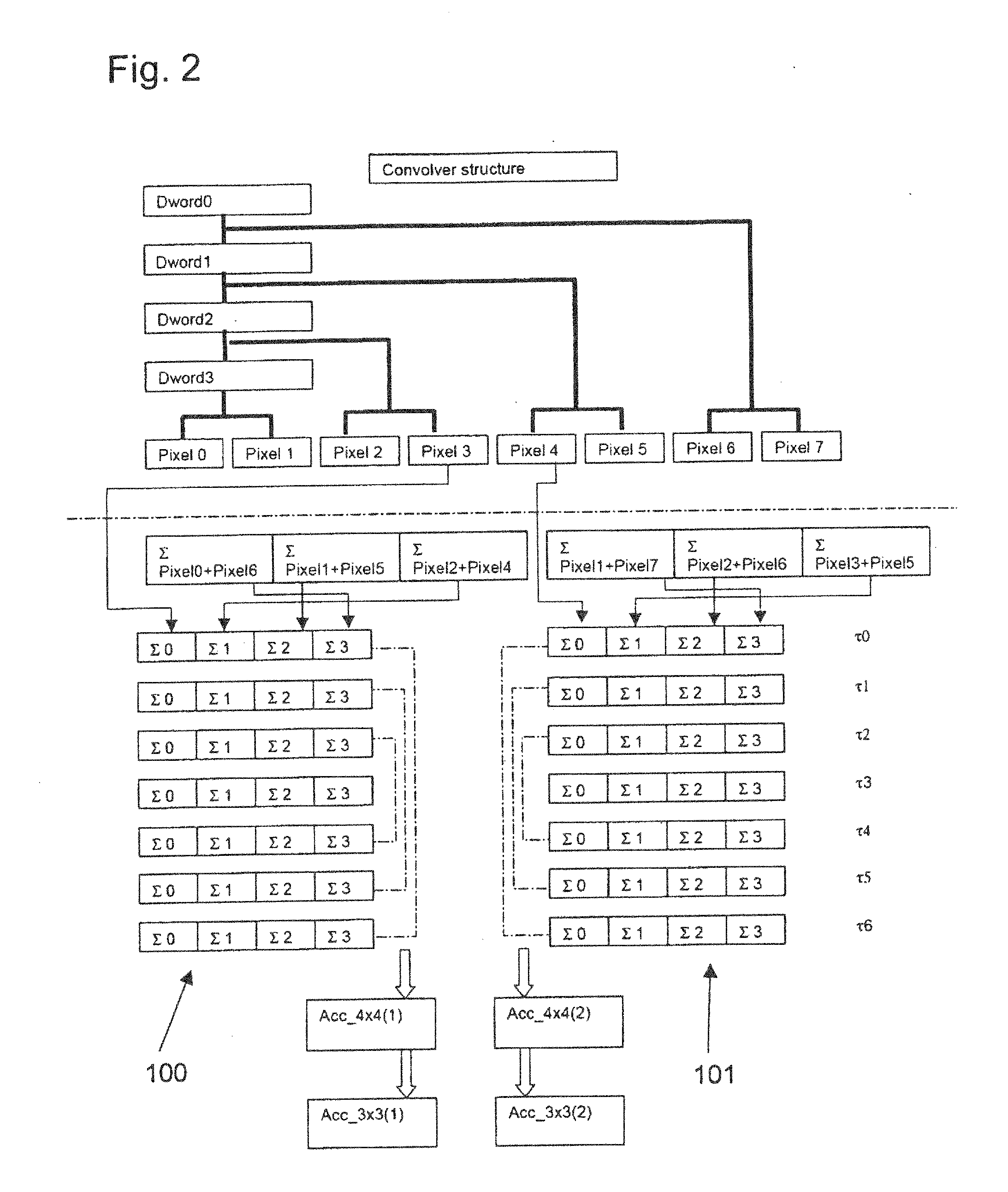
[0030]To achieve the task of creating an optimized memory interface that can support both the operation with DDRAMs as image memories and also the formation of large neighborhoods of a size greater than 7×7 pixels in real time, the raw image data supplied by the sensor is converted by an analog-digital converter (ADU) into digital signals and then stored row-by-row into an image memory made from one or more DDRAMs. After ca. 32 rows have been stored, image data is read from the memory. This process reads short rows with 16 pixel lengths from the image memory and writes these into a fast dual-port RAM that in turn fills a register structure. This scheme makes it possible to reduce the load on the image memory. The resulting data rate during reading is only slightly higher than the data rate of the sensor. In addition, a data rate that is higher by the factor 4 to 8 is achieved at the output for the use of a fast dual-port RAM that is relatively small and thus can be integrated well. ...


PUM


Abstract

A digital image-processing device with a Bayer sensor and an image memory is provided in which the image data of the sensor is written into an image memory, and from this image memory, image data in the Bayer format with a length L and a width B is written continuously into a data buffer, and in which the sample values are combined by means of a computational device with the help of adders, in each case symmetrically to a central point of one or more (2n+1)×(2n+1) neighborhoods, and one or more (n+1)×(n+1) matrices are derived by means of the computational device, and from this (n+1)×(n+1) matrix or these matrices, with the help of additional adders, at least one n×n matrix is formed, and a first color component is in each case calculated from this by means of an adder network.

Description

FIELD OF THE INVENTION[0001]The invention relates, in general, to the processing of color images, in particular, the processing of raw data into displayable formats.BACKGROUND OF THE INVENTION[0002]Currently, typical color image sensors nearly all work with a so-called Bayer matrix or with Bayer sensors. In such sensors a color filter arrangement is arranged on the sensor surface, wherein a color filter for a certain color is inserted in front of each pixel and the colors are weighted differently. The most common are RGB color filters, wherein green pixels are twice as frequent as blue and red.SUMMARY OF THE INVENTION[0003]The raw data of such an image, however, is not displayable on standard displays. For this purpose, a conversion is generally performed wherein the signals of several pixels of the sensor are interpolated. Here there is generally the problem that such conversions can generate artifacts, such as color fringes, or are computationally intensive, so that among other th...

Claims


Application Information

Patent Timeline
IPC IPC(8): H04N5/335
CPCH04N9/045G06T3/4015H04N23/843H04N25/134
Inventor RUECKERT, INGOVIETZE, OLIVERIHLEFELD, JOACHIM
Owner BAUMER OPTRONIC
Learn More