Method and apparatus for correcting optical aberrations using a deformable mirror

Inactive Publication Date: 2011-06-09
YEDA RES & DEV CO LTD +1
View PDF12 Cites 17 Cited by
  • Summary
  • Abstract
  • Description
  • Claims
  • Application Information

AI Technical Summary

Benefits of technology

[0009]The present invention provides a method and apparatus that uses an improved deformable mirror in optical systems to change the focus and corrects optical aberrations, such as spherical aberrations, when analyzing objects, particularly moderately thick objects, without the disadvantages associated with existing approaches. Unlike existing optical systems with larger deformable mirrors, the present invention provides a method and apparatus that simply and precisely deforms a deformable mirror to a shape that provides a variable focal plane at varying depths within an object and corrects optical aberrations. In order to simply and precisely achieve the necessary shape function

Problems solved by technology

Many applications employing optical devices are limited by optical aberrations that result from the configuration of the optical device.
A source of optical aberrations that is particularly limiting in the use of optical devices is the object of the optical device.
Spherical aberrations are particularly problematic when analyzing moderately thick objects because they are depth dependent.
The resulting wavefront after reflection in such mirrors can change the focus of the impinging wave, however, they introduce an additional large component of spherical aberrations.
However, they are problematic in that they must be sufficiently large in order to provide space for the actuators, and they are associated with high-ord

Method used


Image

  • Method and apparatus for correcting optical aberrations using a deformable mirror
  • Method and apparatus for correcting optical aberrations using a deformable mirror
  • Method and apparatus for correcting optical aberrations using a deformable mirror

Examples


Embodiment Construction

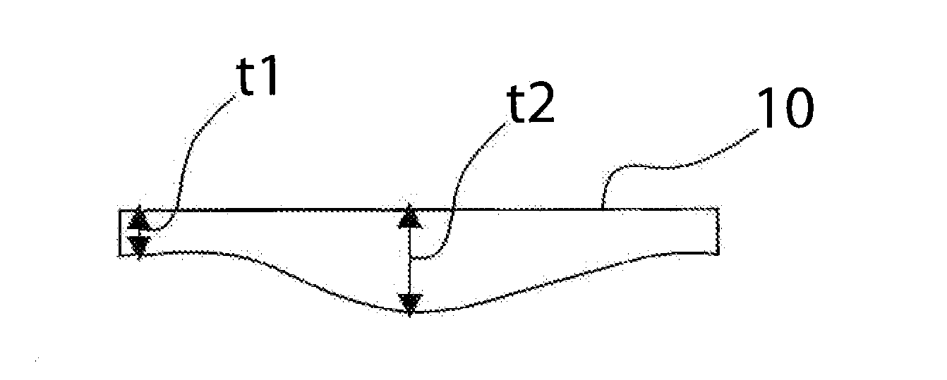
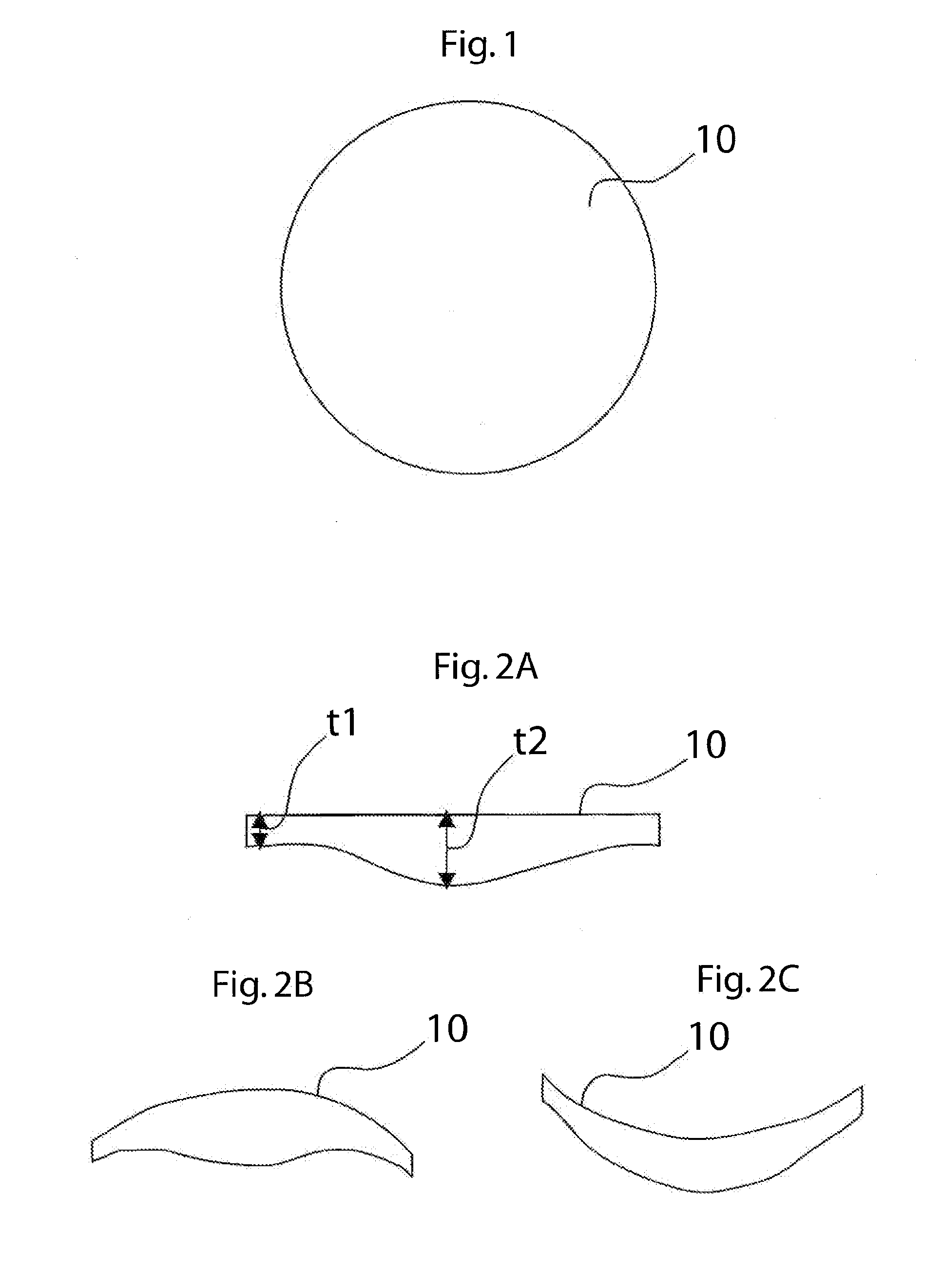
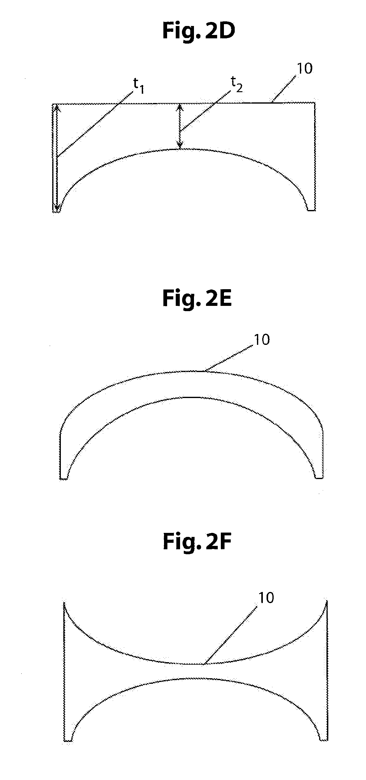
[0035]FIGS. 1 and 2A-2F illustrate a deformable mirror 10 having a variable thickness. In some embodiments, as depicted in FIGS. 2A-2C, deformable mirror 10 is thinner at its periphery than at its center, i.e. , peripheral thickness t1 is smaller than central thickness t2. In other embodiments, as depicted in FIGS. 2D-2F, deformable mirror 10 is thicker at its periphery than at its center, i.e., peripheral thickness t1 is greater than central thickness t2. The relative thickness of the periphery and center of the deformable mirror 10 affects the shape of the deformation that will result when a deforming force is applied to the deformable mirror 10. By modifying the relative thickness of its periphery and center, the deformable mirror 10 can be configured to correct for various effects including, but not limited to, high numerical aperture focus, depth aberrations, thermal lensing, and off-axis aberrations.

[0036]The relative thickness of the periphery and center of the deformable mir...


PUM


Abstract

A method and apparatus for correcting optical aberrations in an optical device using a deformable mirror. An actuator is provided which applies a deforming force to the deformable mirror. By selecting particular thickness profiles of the deformable mirror and force configurations of the actuator, the optical device can be configured to correct for different optical aberrations. The actuator may be configured to apply the deforming force peripherally, centrally, non-centrally or homogenously across the surface of the deformable mirror. The deformable mirror may be a flat disk mirror, a convex mirror, or a concave mirror, and may include a membrane having a variable flexibility. The optical device may be a wide-field microscope, an optical read/write device, laser tweezers, or any other optical device in which correction of optical aberrations is desirable.

Description

CROSS REFERENCE TO RELATED APPLICATIONS[0001]The present application claims the benefit of U.S. Provisional Patent Application Ser. NO. 61 / 024,726, filed Jan. 30, 2008, the contents of which are hereby incorporated by reference in their entirety.FIELD OF THE INVENTION[0002]The invention relates generally to a method and apparatus for correcting optical aberrations. More specifically, the invention relates to a method and apparatus for correcting optical aberrations using a deformable mirror.BACKGROUND OF THE INVENTION[0003]Many applications employing optical devices are limited by optical aberrations that result from the configuration of the optical device. The term “optical aberrations” includes deviations from the correct function of the optical device that result from disruptions and distortions of optical paths associated with the device. A source of optical aberrations that is particularly limiting in the use of optical devices is the object of the optical device. The object, o...

Claims


Application Information

Patent Timeline
IPC IPC(8): G02B7/188
CPCG02B27/0068G02B26/0825
Inventor KNER, PETERAGARD, DAVID A.KAM, ZVISEDAT, JOHN W.
Owner YEDA RES & DEV CO LTD
Why Eureka
Try Eureka