
System and method of deicing and prevention or delay of flow separation over wind turbine blades

a technology of wind turbine blades and flow separation, applied in the field of wind turbines, can solve the problems of loss of pressure, decline in aerodynamic efficiency of wind turbines, and ice collection on wind turbine blades not only contributes to loss of pressure, but also is hazardous, so as to reduce or eliminate the collection of ice

Active Publication Date: 2011-06-09
GENERAL ELECTRIC CO
View PDF3 Cites 26 Cited by
  • Summary
  • Abstract
  • Description
  • Claims
  • Application Information

AI Technical Summary

Benefits of technology

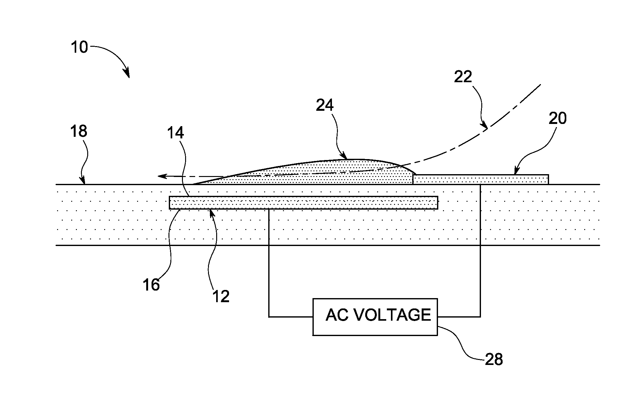
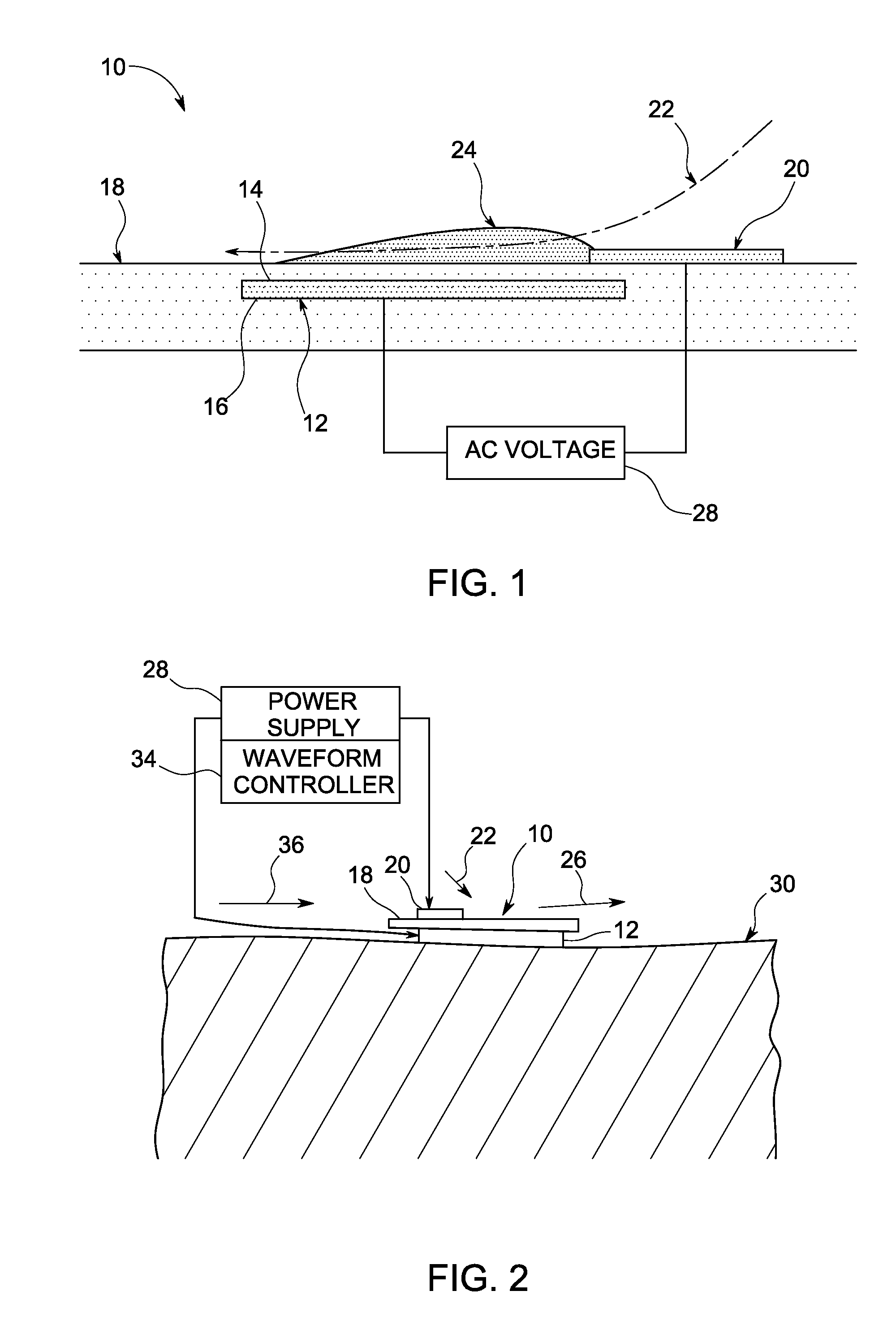
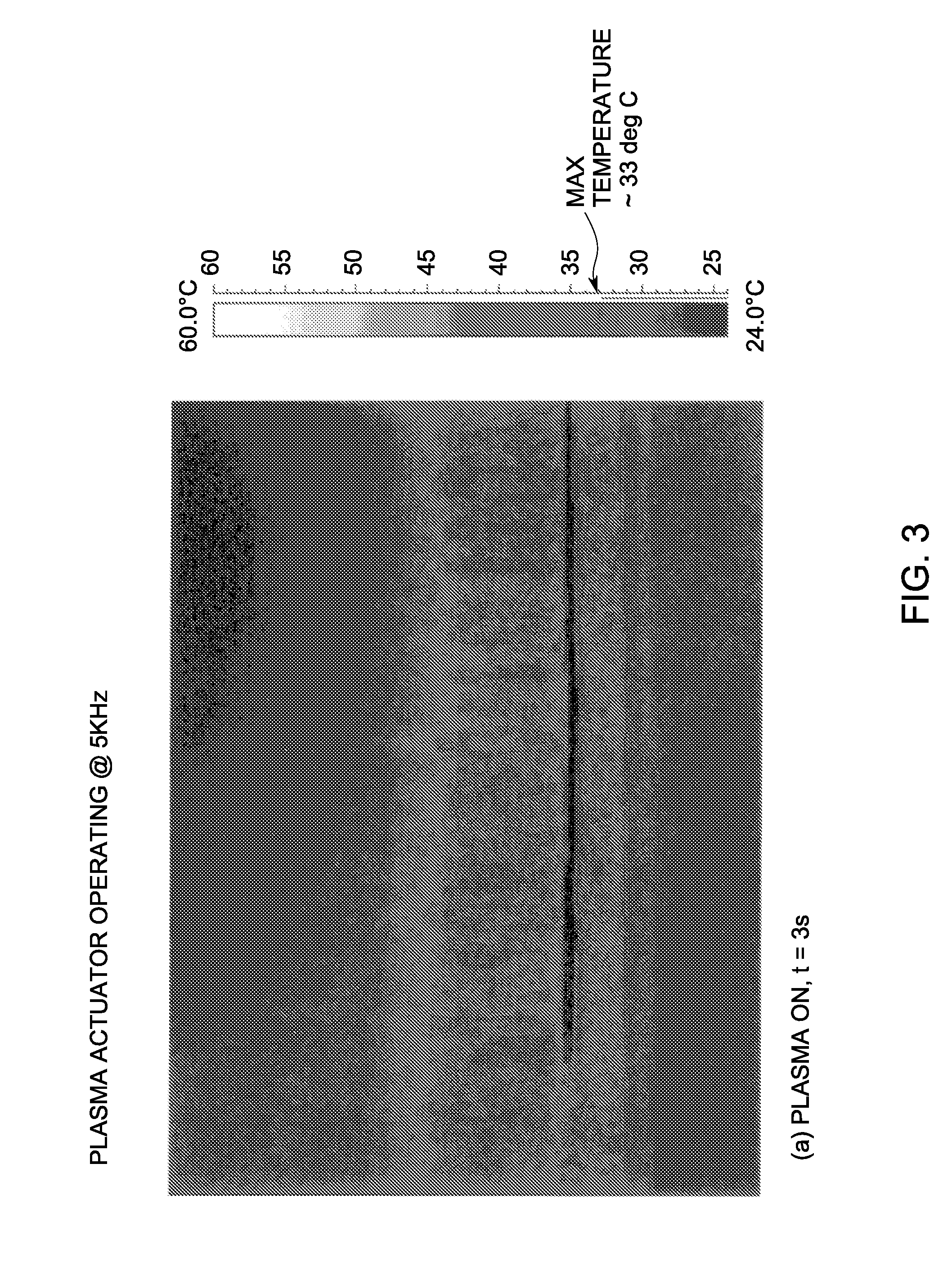
[0006]Briefly, in accordance with one embodiment of the invention, a method of deicing a wind turbine blade comprises applying an active plasma actuator to a desired portion of the wind turbine blade, and electrically energizing the plasma actuator to ionize the air in the vicinity of the plasma actuator such that the surface temperature of the wind turbine blade in the vicinity of the plasma actuator is increased sufficiently to reduce or eliminate the collection of ice on the desired portion of the wind turbine blade.
[0007]According to another embodiment, a system for deicing a wind turbine blade comprises an active plasma actuator applied to a desired portion of the wind turbine blade. An electrical power supply energizes the plasma actuator such that the air in the vicinity of the plasma actuator is ionized to increase the surface temperature of the wind turbine blade in the vicinity of the plasma actuator sufficiently to reduce or eliminate the collection of ice on a desired portion of the wind turbine blade.

Problems solved by technology

This characteristic contributes to loss of pressure and hence a decline in aerodynamic efficiency of a wind turbine.
In cold areas, collection of ice on the wind turbine blades not only contributes to loss of pressure, but also is hazardous.
Currently, there are no techniques used to overcome boundary-layer separation and simultaneously deice wind turbine blades.
Vortex generators have been used to passively delay flow separation; but a major disadvantage to this solution is the vortex generator enhanced flow, even in situations where delaying flow separation is no longer desired.

Method used


Image

  • System and method of deicing and prevention or delay of flow separation over wind turbine blades
  • System and method of deicing and prevention or delay of flow separation over wind turbine blades
  • System and method of deicing and prevention or delay of flow separation over wind turbine blades

Examples


Embodiment Construction

[0018]The embodiments described herein with reference to the figures are directed to methods for controlling boundary layer separation and collection of ice on wind-turbine blades using an active plasma actuator. An active plasma actuator is a device that uses electricity to ionize air. The gradient in electric field results in a body force which acts on the external flow and imparts momentum to the fluid particles. It can also provide a surface temperature increase, which can be controlled by adjusting the operation frequency of the device. The plasma actuator device applications described herein can advantageously modify the boundary layer separation through ionization of air to mitigate flow losses and increase the surface temperature to enhance deicing of wind-turbine blades, among other things.

[0019]Unless defined otherwise, technical and scientific terms used herein have the same meaning as is commonly understood by one of skill in the art to which this invention belongs. The ...


PUM


Abstract

A system for deicing a wind turbine blade includes an electrically powered active plasma actuator applied to a desired portion of a wind turbine blade. The activated plasma actuator energizes the air in the vicinity of the plasma actuator to increase the surface temperature of the wind turbine blade in the vicinity of the plasma actuator sufficiently to reduce or eliminate the collection of ice on a desired portion of the wind turbine blade.

Description

BACKGROUND[0001]The invention relates generally to wind turbines, and more specifically to use of a plasma actuator that operates without an external source of air other than ambient air to modify wind turbine boundary layer separation to energize retarded flows and to reduce the collection of ice over wind turbine blades.[0002]Boundary layer separation takes place over highly curved surfaces for flows at high-angles of attack. This characteristic contributes to loss of pressure and hence a decline in aerodynamic efficiency of a wind turbine. In cold areas, collection of ice on the wind turbine blades not only contributes to loss of pressure, but also is hazardous.[0003]Different techniques have been employed to modify the boundary layer interaction to control flow characteristics. Many of these well known techniques use passive methods and devices, while some others use piezo electric surface modifications for flow control. One known technique employs Dielectric Bather Discharge (D...

Claims


Application Information

Patent Timeline
Patent Type & Authority Applications(United States)
IPC IPC(8): F03D11/00
CPCF03D11/0025F05B2240/122F03D1/0675Y02E10/722Y02E10/721F05D2270/172F03D80/40F05B2240/3062Y02E10/72
Inventor SADDOUGHI, SEYED GHOLAMALIBADDING, BRUCE JOHNGIGUERE, PHILIPPEBOESPFLUG, MATTHEW PATRICKBENNETT, JR., GROVER ANDREWGUPTA, ANURAG
Owner GENERAL ELECTRIC CO
Learn More