
Turbine components for engines and methods of fabricating the same

a technology for engine components and turbine blades, applied in the field of engine components, can solve the problems of high cost of gas turbine disks fabricated using individually cast and inserted single crystal airfoils, and the degradation of turbine engine components at higher temperatures, and achieve the effects of improving the quality of engine components, reducing the cost of gas turbine disks, and improving the service li

Inactive Publication Date: 2011-06-09
HONEYWELL INT INC
View PDF17 Cites 116 Cited by
  • Summary
  • Abstract
  • Description
  • Claims
  • Application Information

AI Technical Summary

Benefits of technology

The patent text describes methods and components for fabricating components with a directionally solidified microstructure or single crystal microstructure. The methods involve depositing metal powder over a seed crystal and scanning it with a laser beam to melt or sinter the metal powder and form an initial layer with the predetermined orientation. Additional metal powder is then deposited and scanned to form a successive layer with the same orientation. This process is repeated until the final shape of the component is achieved. The components made using these methods have improved properties and can be used in engines.

Problems solved by technology

Some turbine engine components, such as turbine blades and disks, may experience greater degradation at higher temperatures.
However, gas turbine disks fabricated using individually cast and inserted single crystal airfoils tend to be expensive.
Additionally, a fabrication period for these components may take several months, which may be undesirable because component designs may be modified for performance improvement at some point during the fabrication period.

Method used


Image

  • Turbine components for engines and methods of fabricating the same
  • Turbine components for engines and methods of fabricating the same
  • Turbine components for engines and methods of fabricating the same

Examples


Embodiment Construction

[0014]The following detailed description is merely exemplary in nature and is not intended to limit the inventive subject matter or the application and uses of the inventive subject matter. Furthermore, there is no intention to be bound by any theory presented in the preceding background or the following detailed description.

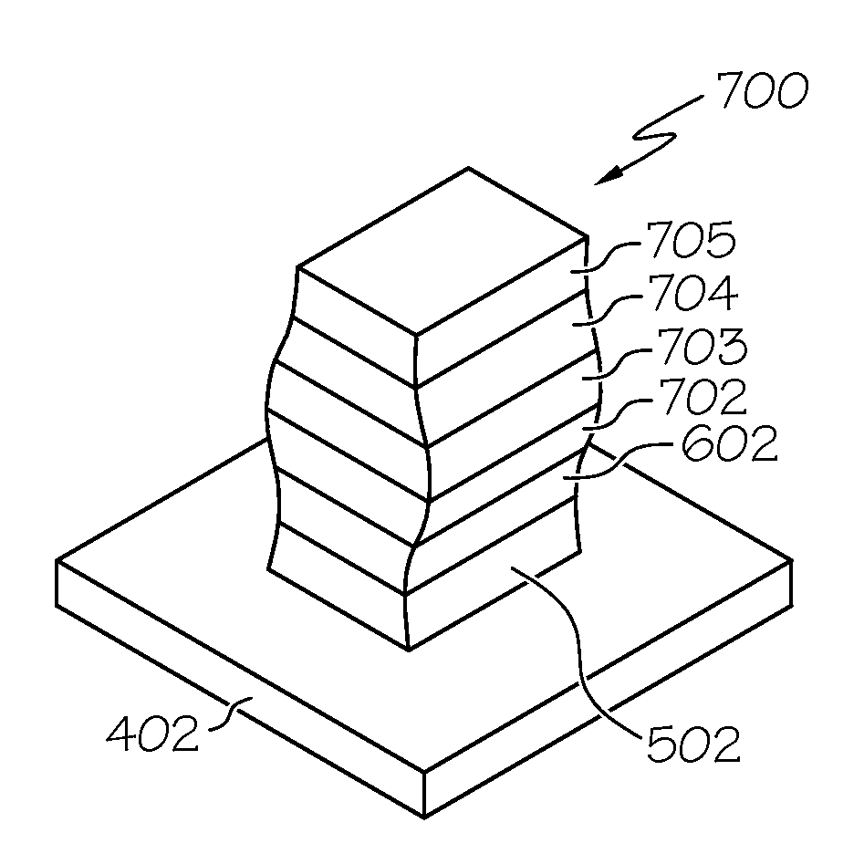
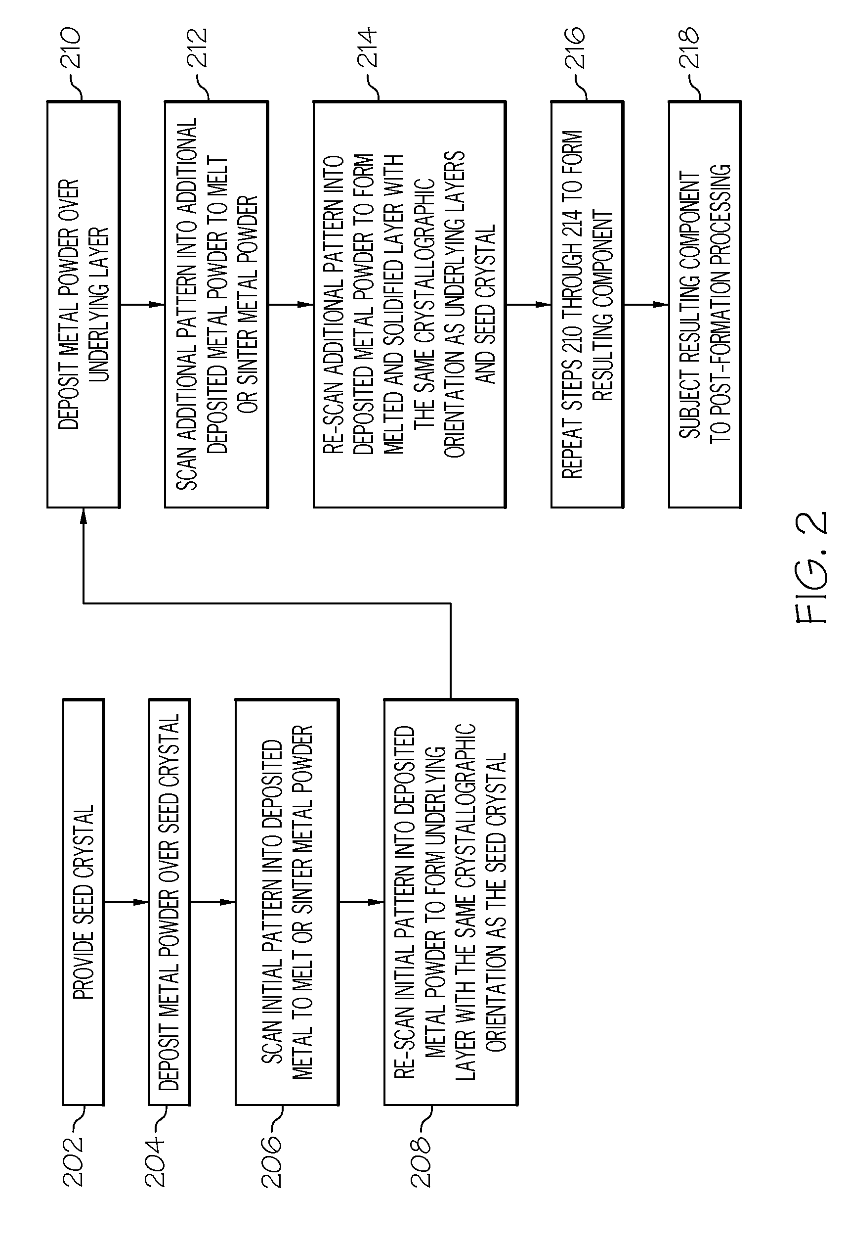
[0015]Generally, the inventive subject matter relates to improved methods for manufacturing single crystal microstructure components or directionally solidified microstructure components. The method includes depositing a relatively thin layer of metal powder over a seed crystal having a predetermined primary orientation, scanning an initial pattern into the thin layer of metal powder with a laser beam to sinter or melt the metal powder in the initial pattern and adhere the metal powder to the seed crystal, raising a surface on which the scanning occurred (“scan surface”) above a surface of a powder bed, and re-scanning the initial pattern with the laser beam to ...


PUM

PropertyMeasurementUnit
total thicknessaaaaaaaaaa
thicknessaaaaaaaaaa
poweraaaaaaaaaa

Abstract

A method is provided that includes depositing metal powder over a seed crystal having a predetermined primary orientation, scanning an initial pattern into the metal powder to melt or sinter the deposited metal powder, and re-scanning the initial pattern to re-melt the scanned metal powder and form an initial layer having the predetermined primary orientation. The method further includes depositing additional metal powder over the initial layer, scanning an additional pattern into the additional metal powder to melt or sinter at least a portion of the additional metal powder, re-scanning the additional pattern to re-melt a portion of the initial layer and the scanned deposited additional metal powder to form a successive layer having the predetermined primary orientation, and repeating the steps of depositing additional metal powder, scanning the additional pattern, and re-scanning the additional pattern, until a final shape of the component is achieved.

Description

TECHNICAL FIELD[0001]The inventive subject matter generally relates to engines, and more particularly relates to turbine components for engines and methods of fabricating the turbine components.BACKGROUND[0002]Turbine engines are used as the primary power source for various kinds of aircraft. The engines may also serve as auxiliary power sources that drive air compressors, hydraulic pumps, and industrial electrical power generators. Most turbine engines generally follow the same basic power generation procedure. Compressed air is mixed with fuel and burned, and the expanding hot combustion gases are directed against stationary turbine vanes in the engine. The vanes turn the high velocity gas flow partially sideways to impinge onto turbine blades mounted on a rotatable turbine disk. The force of the impinging gas causes the turbine disk to spin at high speed. Jet propulsion engines use the power created by the rotating turbine disk to draw more air into the engine, and the high veloc...

Claims


Application Information

Patent Timeline
Patent Type & Authority Applications(United States)
IPC IPC(8): B32B15/02B22F7/02
CPCB22F3/1055Y10T428/12028B22F7/08B22F5/009C30B13/00C30B29/52Y02P10/25B22F10/28B22F10/64B22F10/62B22F10/36B22F12/41
Inventor MORRIS, MARK C.STRANGMAN, TOMHU, YIPING
Owner HONEYWELL INT INC
Learn More