Eureka AIR delivers breakthrough ideas for toughest innovation challenges, trusted by R&D personnel around the world.

Perfusion device

Inactive Publication Date: 2011-06-09
UNIVERSITY OF LIMERICK
View PDF14 Cites 40 Cited by
  • Summary
  • Abstract
  • Description
  • Claims
  • Application Information

AI Technical Summary

Benefits of technology

In one embodiment, the filtering portion has an asymmetrical edge for improved retrieval to enable improved device deliverability and extraction.
In one embodiment, the support is adapted to allow gradual and controlled inflation of the perfusion balloon.

Problems solved by technology

An acute complication of carotid angioplasty and stenting relates to the distal embolisation of plaque particles during the endovascular procedure, with the risk of definitive stroke.

Method used


Image

  • Perfusion device
  • Perfusion device
  • Perfusion device

Examples


Embodiment Construction

The invention will be more clearly understood from the following description of some embodiments thereof, given by way of example only with reference to the accompanying drawings in which:—

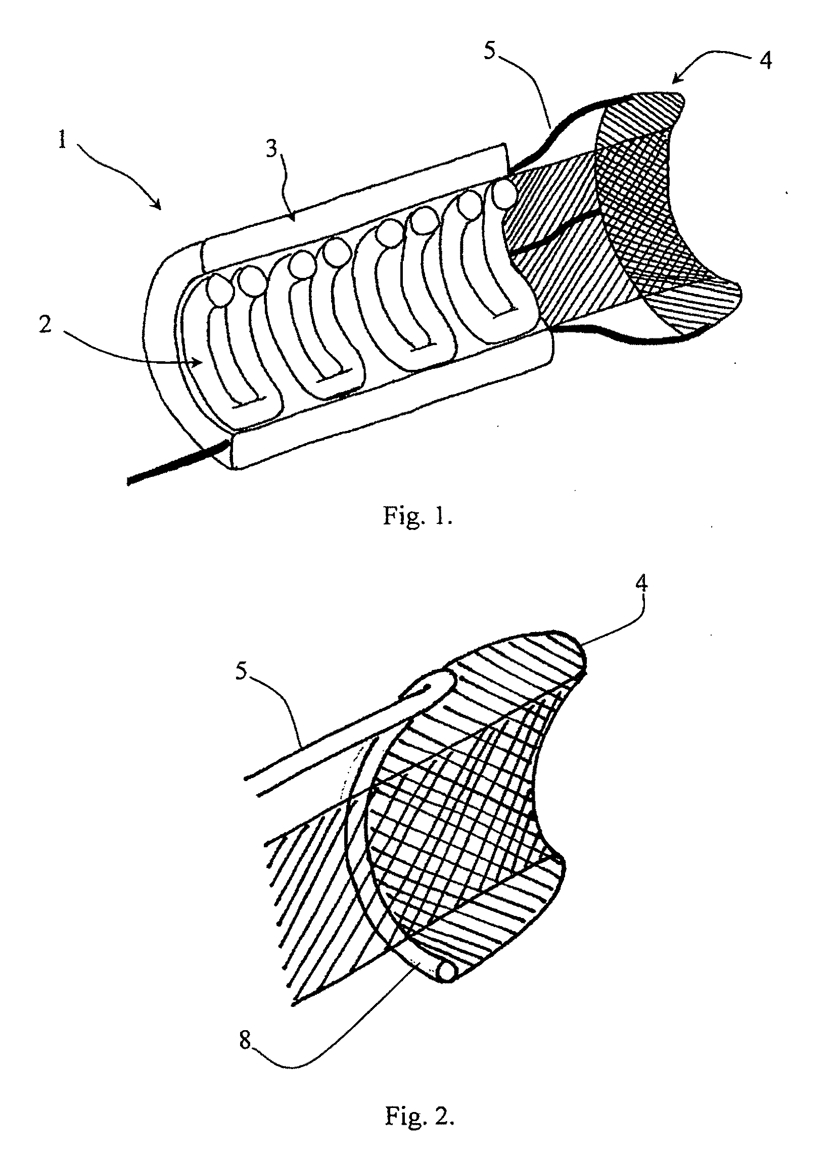
FIG. 1 is a cut-away perspective view of a perfusion device of the invention when deployed, the device having an annular balloon and a support rib cage balloon and an embolic protection filter;

FIG. 2 is a partly cut-away perspective view showing an alternative filter, having a wall apposition support mechanism using an inflated ring balloon;

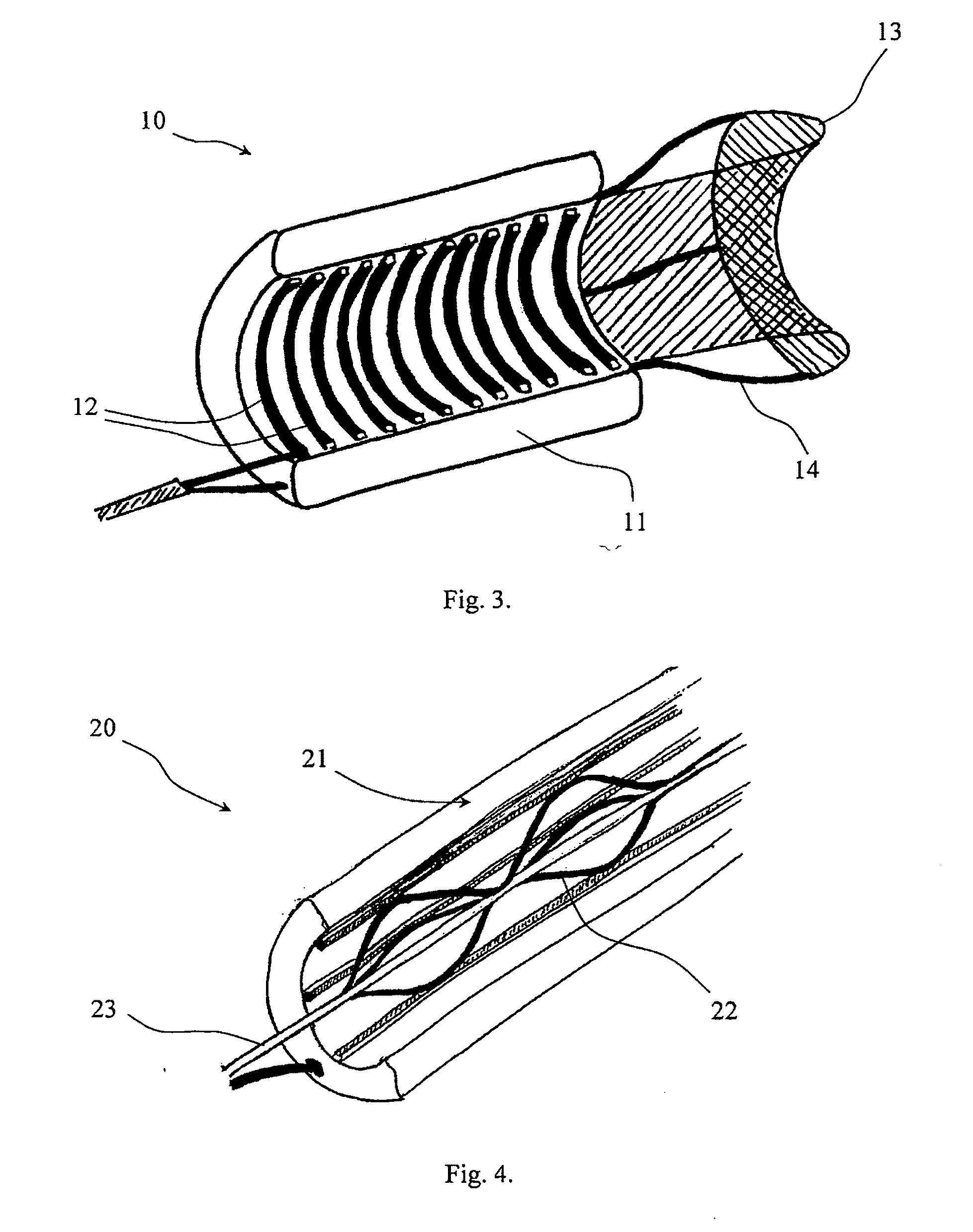
FIG. 3 is a cut-away perspective view of an alternative device, in this case having a metallic support coil;

FIG. 4 is a partly cut away view showing part of an alternative device, in this case having a mechanical support with arched metal members when fully deployed;

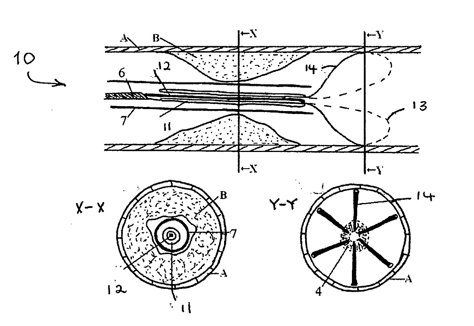
FIG. 5 is a longitudinal cross-sectional view showing site of occlusion of plaque B within an artery wall A;

FIG. 6 is a longitudinal cross-sectional diagram showing positioning of the device of FIG....


PUM


Abstract

A vascular filter device (1) has a perfusion balloon (3) with a through-hole for blood flow. There is a distal filter (4) for trapping emboli, and the filter (4) is configured to filter an annular cross-sectional area extending from a vessel wall, while leaving an un-filtered central passageway. The filter (4) may be substantially frusto-conical in shape when deployed, and have a proximal tubular part (41) which is attached to the perfusion balloon or a support for the perfusion balloon. The filter has a retainer (5) to retain an end of the filter in an in-use position abutting a vessel wall. The retainer may comprise wires (5) or an inflated ring (8). The device may have an internal support (2, 12, 22, 96, 112) for the perfusion balloon (3, 11, 21, 95, 111). The balloon inflates and expands the inner arterial wall, and the filter captures emboli released during the procedure while leaving a channel that allows blood to flow to tissues distal to the blockage, maintaining antegrade flow. This may prevent the onset of an ischemic stroke or other perioperative neurological events.

Description

INTRODUCTION1. Field of the InventionThe invention relates to medical devices, and more particularly to devices for insertion in blood vessels and having a perfusion balloon for expanding to press against the vessel wall.2. Prior Art DiscussionThe balloon catheter is well established as an important medical device. The device can be used on its own to open a blocked artery or it can be used to deliver a stent (a small wire mesh tube) to the offending artery. The stent will expand when the balloon expands and is left in the artery acting as a scaffold to keep it open.Carotid angioplasty and stenting is being used widely to treat severe carotid obstructive disease. An acute complication of carotid angioplasty and stenting relates to the distal embolisation of plaque particles during the endovascular procedure, with the risk of definitive stroke. Studies using in vivo monitoring (such as Magnetic Resonance Imaging (MRI), Computed Tomography (CT) or Transcranial Doppler) have shown that...

Claims


Application Information

Patent Timeline
IPC IPC(8): A61M29/02
CPCA61F2230/008A61F2230/0093A61F2230/0006A61F2/958A61F2002/018A61F2/013
Inventor WALSH, MICHAELO'CONNELL, BARRYMCGLOUGHLIN, TIMOTHYLAWLOR, MICHAEL V.O'DONNELL, MICHAEL
Owner UNIVERSITY OF LIMERICK
Why Eureka
Eureka Blog
Learn More