Percutaneous Retrievable Vascular Filter

a filter and vascular technology, applied in the field of filtering within the vessel, can solve the problems of pulmonary embolism, thrombotic occlusion, and development of dvt is venostasis

Inactive Publication Date: 2011-06-09
MERIT MEDICAL SYST INC
View PDF105 Cites 32 Cited by
  • Summary
  • Abstract
  • Description
  • Claims
  • Application Information

AI Technical Summary

Benefits of technology

[0010]It is an object of the present invention to provide a filter comprising a first tube and a second tube. The first tube has a plurality of a first set of slots, a plurality of a second set of slots, and a plurality of a first set of expandable legs. Each leg of the first set has an end secured to the first tube and a free end. The second tube has a plurality of a second set of expandable legs and a plurality of a third set of expandable legs. Each leg of the second set has an end secured to the second tube and a free end. Each leg of the third set comprises an expandable segment and has both ends secured to the second tube. Each slot of the first set of slots is positioned at a radial position on the first tube allowing for deployment of each expandable leg of the second set. Each slot of the second set of slots is positioned at a radial position on the first tube allowing for deployment of the expandable segment in each leg of the third set, the slots being oriented parallel to the cylindrical axis of the first tube. The second tube's external diameter is less than the first tube's internal diameter. The second tube is inserted into the first tube such that the free end of each leg in the first set is oriented in a direction opposite to the free end of each leg in the second set. The filter may be encased in a catheter in an undeployed state. Each expandable leg of the first and second sets can be deployed and form a cage. The cage may form a sphere shape when the expandable legs of the first and second set are deployed; the expandable segment of each expandable leg in the third set may form a curvilinear shape when deployed; the barb on the end of free end may be inserted into a vessel wall when the filter is deployed. Each expandable leg of the first set and second set may have at least one barb on the free end. At least one end of the first tube and / or the second tube may have at least one notch.

Problems solved by technology

Pulmonary embolism (PE) is a common health problem and a leading cause of death in all age groups.
An important risk factor for the development of DVT is venostasis; common scenarios include bedridden trauma patients and passengers on long airplane flights.
While some vena cava filters are permanently placed in the patient, there are potential complications associated with long-term filter implantation, including thrombotic occlusion of the vena cava, filter migration, filter fragmentation and filter embolization.
The peripheral tether causes a certain degree of patient immobility and increases the risk of infection.
While the versatility of retrievable filters makes them favorable options, in clinical practice, a large number of the retrievable filters are prone to migration and tilt.
Filter tilt seriously reduces the filtering efficiency.
The migration or tilt further makes it difficult or impossible to retrieve the filter.

Method used


Image

  • Percutaneous Retrievable Vascular Filter
  • Percutaneous Retrievable Vascular Filter
  • Percutaneous Retrievable Vascular Filter

Examples


fourth embodiment

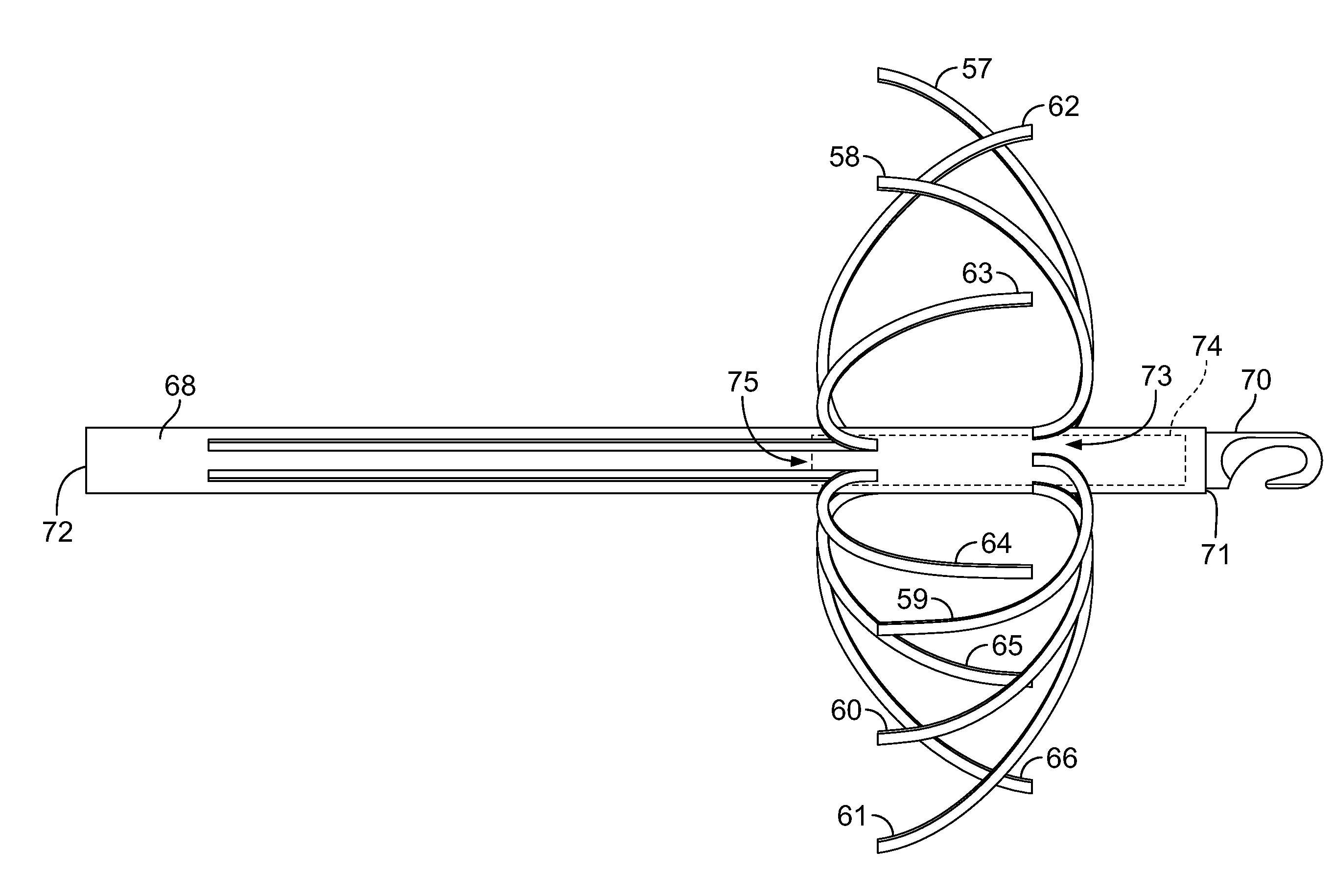
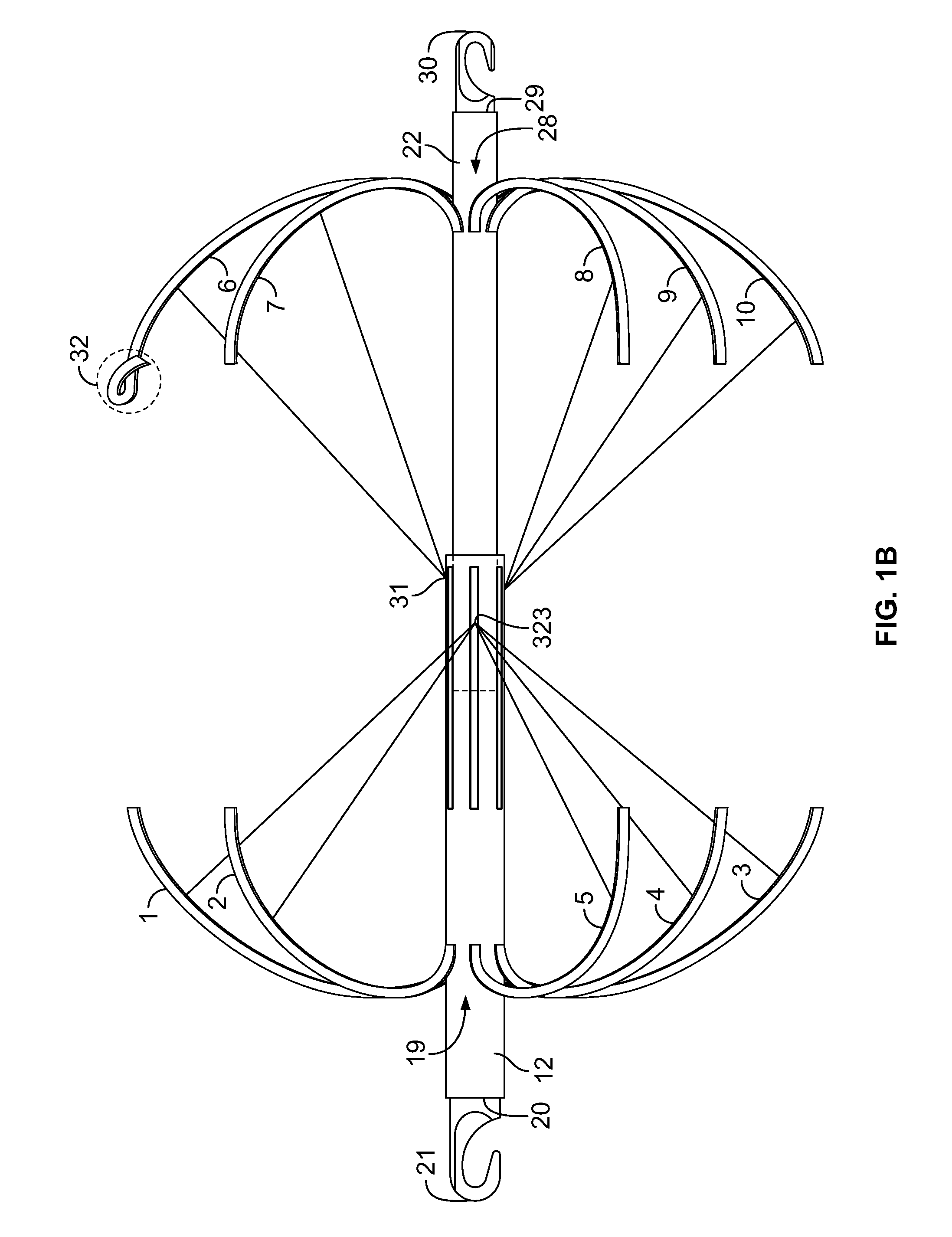
[0089]In a fourth embodiment, the present invention provides a filter comprising a first tube having a plurality of a first set of expandable legs and a plurality of a first set of slots, and a second tube having a plurality of a second set of expandable legs. Each leg of the first set has an end secured to the first tube and a free end, each leg of the second set has an end secured to the second tube and a free end. The free end of each leg in the first set is oriented in a direction opposite to the free end of each leg in the second set. Each slot of the first set on the first tube is positioned at a radial position allowing for deployment of each leg of the second set. The slots are oriented parallel to the cylindrical axis of the first tube. The radial positions of the second set of expandable legs may be the same as or be off-set from the radial positions of the first set of expandable legs. In one embodiment, the radial positions of the second set of expandable legs are off-se...

fifth embodiment

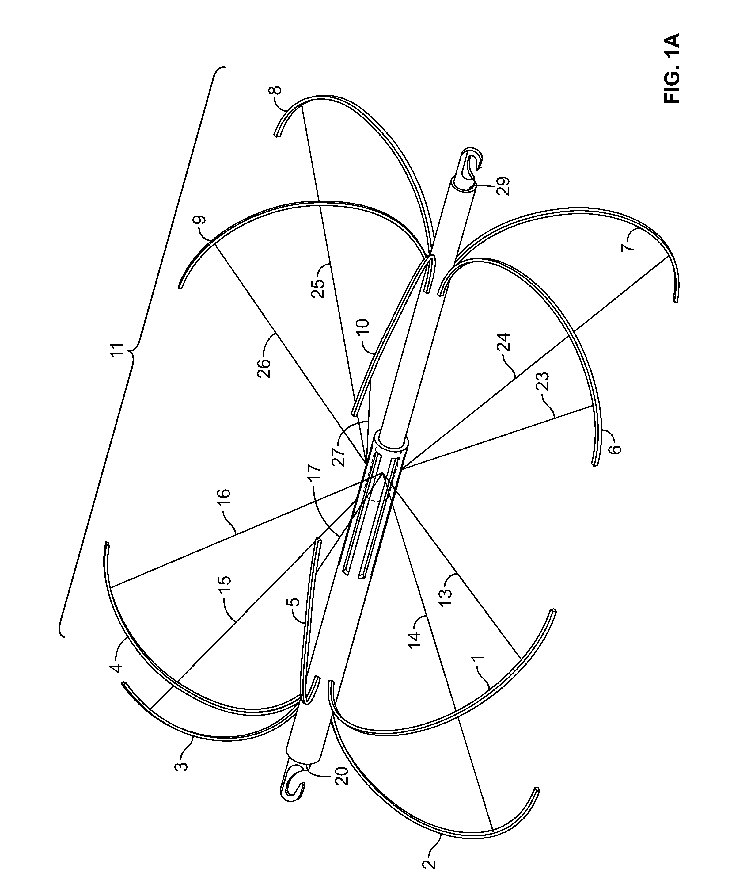
[0090]In a fifth embodiment, the present invention provides a filter comprising a tube having a plurality of a first set of expandable legs, a plurality of a second set of expandable legs and a plurality of a third set of expandable legs. Each leg of the first set, second set and third set has an end secured to the tube and a free end. The free end of each leg is oriented in the same direction. The number of expandable legs in the first, second and third set may be the same or be different. The radial positions of the first set, the second set and the third set of slots may be same or may be different. In a preferred embodiment, the number of expandable legs and the redial positions of the first, second and third set of expandable legs are the same. After deployment, the free end of each leg is oriented in the same direction pointing to the end of the tube distal to the first set of expandable legs. There is at least one notch at the end of the tube proximal to the first set of expa...

sixth embodiment

[0091]In a sixth embodiment, the present invention provides a filter comprising a tube having a plurality of a first set of expandable legs and a plurality of a second set of expandable legs. Each leg of the first set and the second set has an end secured to the tube and a free end. The free end of each leg in the first set is oriented in a direction opposite to the free end of each leg in the second set. Each leg of the first and the second sets is bent inward at the end closest to the tube for easy retrieval of the filter. Each leg of the first and second set may have at least one barb at its free end. The radial positions of the second set of expandable legs may be the same as or be off-set from the radial positions of the first set of expandable legs. A cage may be formed comprising the expandable legs of the first and second sets. The cage may form a sphere shape when the expandable legs of the first and second sets are deployed. At least one end of the tube has at least one no...


PUM


Abstract

Retrievable vena cava filters for the temporary or permanent prevention of Pulmonary embolism (PE) are disclosed. A filter in accordance with the present invention has a tube-within-tube structure with overlapping semi-spheres. The semi-spheres comprise a plurality of expandable legs. The first tube may have a plurality of slots allowing for deployment of a first or second sets of expandable legs on the second tube. The free end of each leg in the first set of expandable legs may be oriented in a direction the same as or opposite to the free end of each leg in the second set. The filter may also be formed from a single tube. In certain embodiments, the filter of the present invention can be retrieved from either end.

Description

CROSS REFERENCE TO RELATED APPLICATION[0001]This application claims the benefit under 35 U.S.C. §119(e) of the U.S. Provisional Application Nos. 61 / 180,041 (filed on May 20, 2009) and 61 / 263,712 (filed Nov. 23, 2009). This application is a continuation-in-part of U.S. application Ser. No. 12 / 203,515, filed on Sep. 3, 2008, which claims the benefit under 35 U.S.C. §119(e) of the U.S. Provisional Application No. 60 / 967,704, filed on Sep. 7, 2007. This application also claims priority to PCT / US2010 / 023100, filed on Feb. 3, 2010, which claims priority to U.S. Provisional Application Nos. 61 / 149,482 (filed on Feb. 3, 2009) and 61 / 180,041 (filed on May 20, 2009).FIELD OF THE INVENTION[0002]The present invention relates to filters within a vessel. In particular, the present invention relates to retrievable vena cava filters which may be permanent or retrievable.BACKGROUND OF THE INVENTION[0003]Pulmonary embolism (PE) is a common health problem and a leading cause of death in all age groups...

Claims


Application Information

Patent Timeline
Patent Type & Authority Applications(United States)
IPC IPC(8): A61F2/01
CPCA61B17/221A61F2/01A61F2002/011A61F2002/061A61F2230/0093A61F2002/016A61F2230/005A61F2230/0076A61F2230/008A61F2250/0059A61F2/011A61F2/012
Inventor HALLISEY, MICHAEL J.
Owner MERIT MEDICAL SYST INC
Why Eureka
Try Eureka