Multi-level liquid level magnetic sensor

a magnetic sensor and liquid level technology, applied in liquid/fluent solid measurement, instruments, machines/engines, etc., can solve the problems of cost and reliability problems of a multiple float system, and achieve the effect of expanding the operating range of a single floa

Inactive Publication Date: 2011-06-16
ILLINOIS TOOL WORKS INC
View PDF14 Cites 26 Cited by
  • Summary
  • Abstract
  • Description
  • Claims
  • Application Information

AI Technical Summary

Benefits of technology

[0004]The present invention employs a single float moving past a series of reed switches. The reed switches are attached to a resistive ladder to provide an increasing voltage as the float rises and different reed switches are closed. An improved magnet design in the float and a staggering of parallel reed switches is used to obtain a “make before break” operation of the reed switches allowing an expanded operating range of a single float without the possibility of non-monotonic behavior in the output signal.

Problems solved by technology

A drawback to this design is the cost and reliability problems associated with a multiple float system.

Method used


Image

  • Multi-level liquid level magnetic sensor
  • Multi-level liquid level magnetic sensor
  • Multi-level liquid level magnetic sensor

Examples


Embodiment Construction

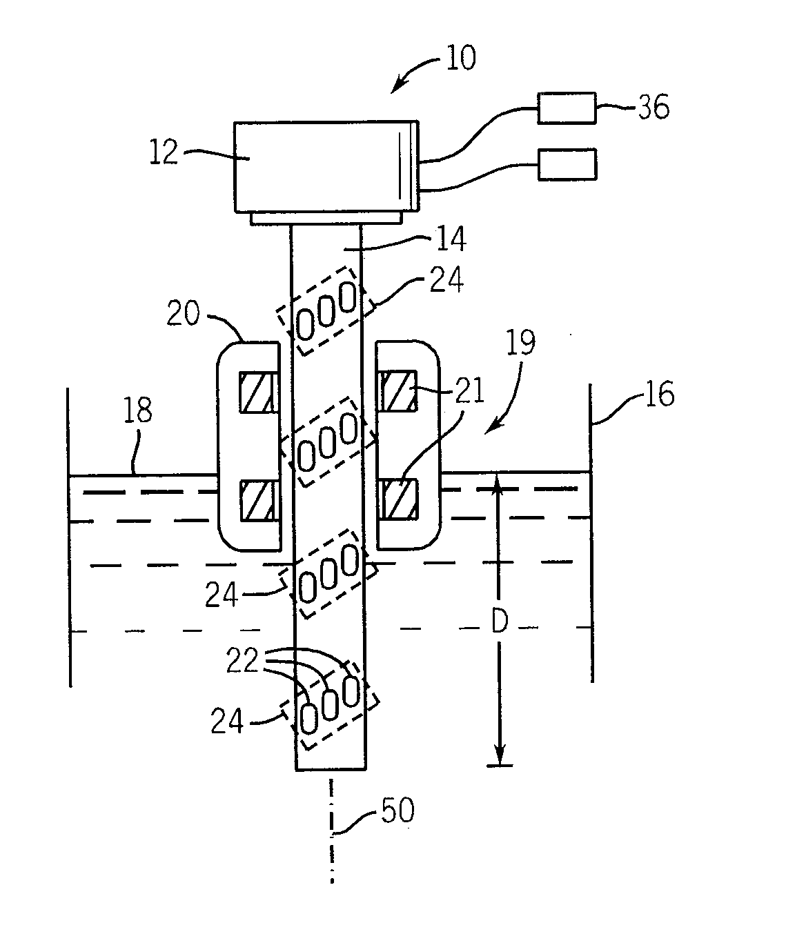
[0026]Referring now to FIG. 1, a liquid level sensor 10 includes a mounting bracket 12 fixing a central shaft 14 in vertical orientation in a tank 16 holding a liquid 18 such as urea.

[0027]A float 20 rests in the liquid 18 to move freely up and down about the shaft 14 with respect to the mounting bracket 12. The float 20 may be hollow to provide an inner air chamber sealed against the liquid 18 or maybe made of a buoyant material that resists the liquid 18. In either case, the float 20 is designed so that its density is less than that of the liquid 18 so that the float 20 is sufficiently buoyant so that a portion rises above the surface of the liquid 18 and so that the entire float 20 rises and falls to track the surface of the liquid 18 and thus the height D of the liquid from an arbitrary reference point (typically a bottom of the tank 16).

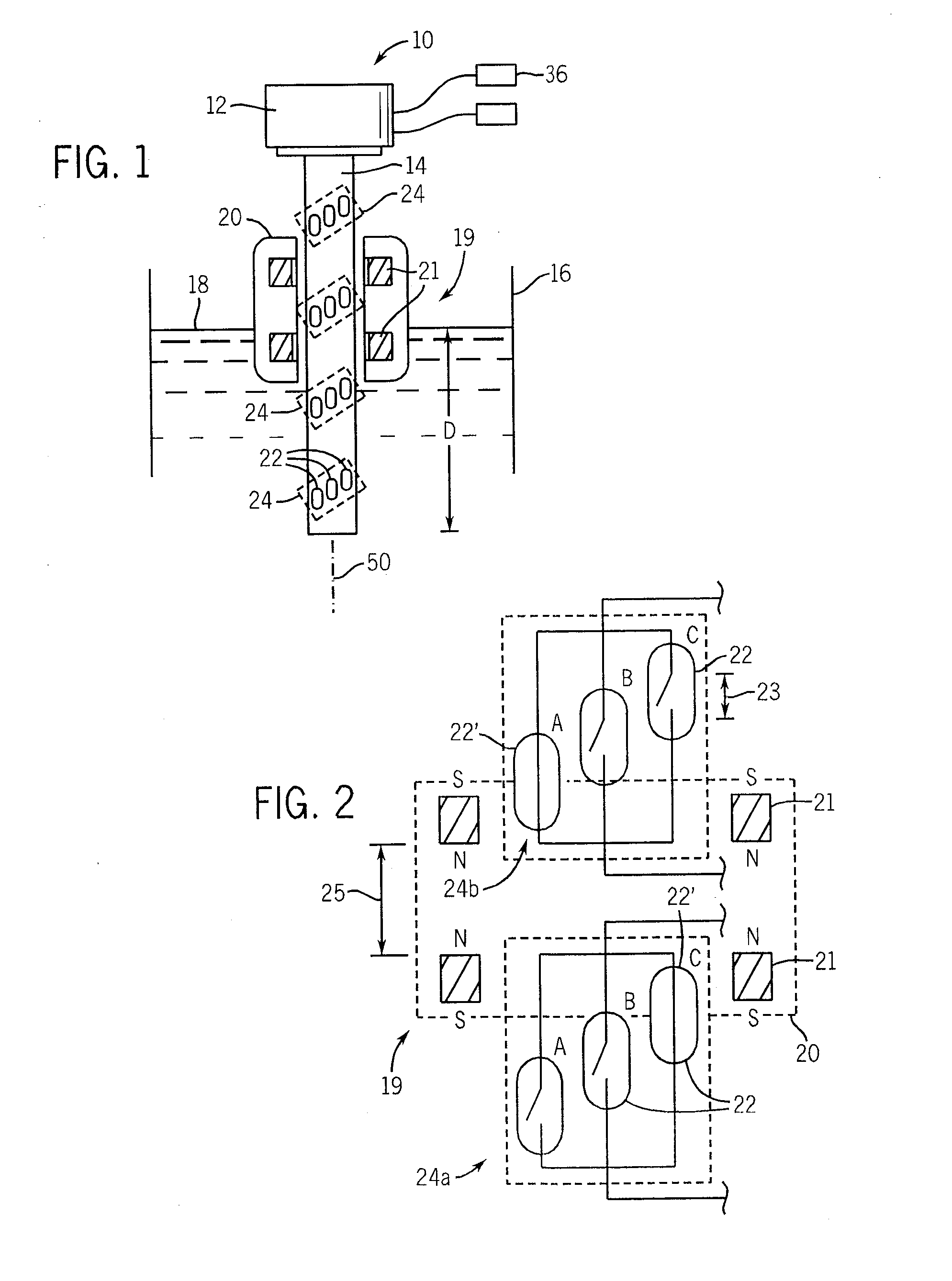
[0028]The float 20 may incorporate two toroidal magnets 21 forming a magnet element 19 positioned about the shaft 14 and separated axially alon...


PUM


Abstract

A liquid level sensor employs a set of axially displaced magnetic sensing switches and a magnet on a float that may rise and fall on liquid level to activate and deactivate the switches. The switches and magnet are configured so that movement of the magnetic float activates a new switch before deactivation of an adjacent previously activated switch. An electronic circuit provides a signal based on the uppermost activated switch to provide a signal that is monotonic with liquid level. The design may be readily implemented using reed switches and a resistive ladder.

Description

CROSS REFERENCE TO RELATED APPLICATION[0001]This Non-Provisional Application claims benefit to U.S. Provisional Application Ser. No. 61 / 057,073 filed May 29, 2008 hereby incorporated by reference.FIELD OF THE INVENTION[0002]The present invention relates to fluid level sensors, particularly sensors that may be suitable for use in monitoring urea levels in diesel engine emission control systems using “selective catalytic reduction” (SCR).BACKGROUND OF THE INVENTION[0003]A wide variety of liquid level sensing technologies exist including those using ultrasonic signals, changes in capacitance, and changes in electrical resistance. One type of liquid level sensor employs magnetic reed switches arranged along a column. The reed switches close in the proximity of a magnetic field which may be produced by a magnet held in a float rising and falling with the liquid level. In order to provide a continuous output signal that changes monotonically (that is, always increases and never decreases ...

Claims


Application Information

Patent Timeline
Patent Type & Authority Applications(United States)
IPC IPC(8): G01F23/30
CPCG01F23/74
Inventor RUDD, JEFFREY P.PELLEGRINI, JAMES M.BONENFANT, BRIAN J.
Owner ILLINOIS TOOL WORKS INC
Why Eureka
Try Eureka