Temperature measurement in a chill mold by a fiber optic measurement method

a technology of fiber optic measurement and chill mold, which is applied in the direction of heat measurement, instrumentation, and molds of foundation moulding, can solve the problems of large amount of cabling work, large number and size of thermocouples, and sensors that are also susceptible to electromagnetic fields, so as to improve the local resolution of temperature measurement

Inactive Publication Date: 2011-06-16
SMS DEMAG AG
View PDF4 Cites 9 Cited by
  • Summary
  • Abstract
  • Description
  • Claims
  • Application Information

AI Technical Summary

Benefits of technology

[0010]Temperature detection by means of optical fibers makes it possible to achieve a significant reduction in the amount of cabling work in comparison with the use of thermocouples in the mold. In addition, much less work and much lower cost are required to install the fibers in the copper plate of the mold. The use of light waveguides according to the above method also makes it possible to achieve much greater local resolution than temperature measurement by the previously described systems based on the use of thermocouples in bores. One glass fiber line, for example, can replace more than a hundred thermocouples with their cabling. Nor is there any need for complicated devices to protect the thermocouples and their cabling.
[0012]In another preferred embodiment, the method comprises at least two light waveguide fibers, longitudinally offset from each other, each of which is arranged in a groove. The local resolution of the temperature measurement can be improved even more by this means.

Problems solved by technology

Temperature detection in a mold is a critical problem, which is becoming even more important in the case of casting machines operating at high speed.
The number and size of these thermocouples is limited.
Increasing the number of thermocouples, furthermore, leads to a very large amount of cabling work.
These sensors are also susceptible to the electromagnetic fields caused by electromagnetic brakes or stirrers, for example.
When the copper plates of a mold are to be replaced—a task which must be done at regular intervals—the thermocouples must be disconnected and then reconnected to their cables, which not only requires a great deal of work but also involves the danger of making wrong connections.
These two methods suffer from the disadvantages cited above.
In addition, producing a large number of bores is expensive and time-consuming.
A very large number of thermocouples installed in this way results unfortunately in an extremely large amount of cabling work.
In this form, however, such systems are unsuitable for measuring temperatures in a mold and are not designed for the exact detection of local temperatures in a casting mold.
The technical problem which therefore arises is to find an improved method for measuring temperatures in a mold, especially for measuring them with greater local resolution, namely, a method which requires the least possible amount of installation work and which improves, among other things, the detection of longitudinal cracks and / or through-fractures in the mold.

Method used


Image

  • Temperature measurement in a chill mold by a fiber optic measurement method
  • Temperature measurement in a chill mold by a fiber optic measurement method
  • Temperature measurement in a chill mold by a fiber optic measurement method

Examples


Embodiment Construction

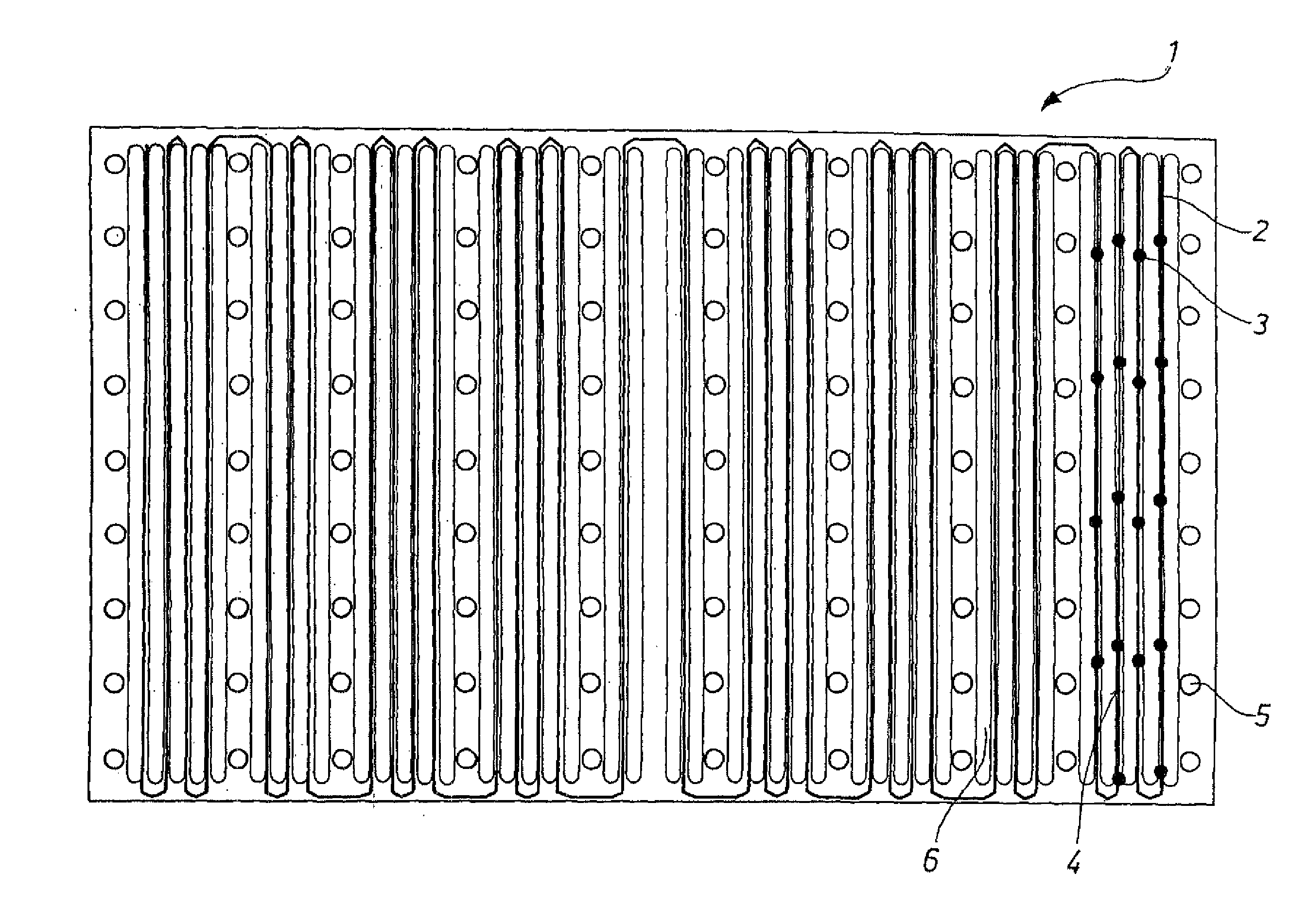
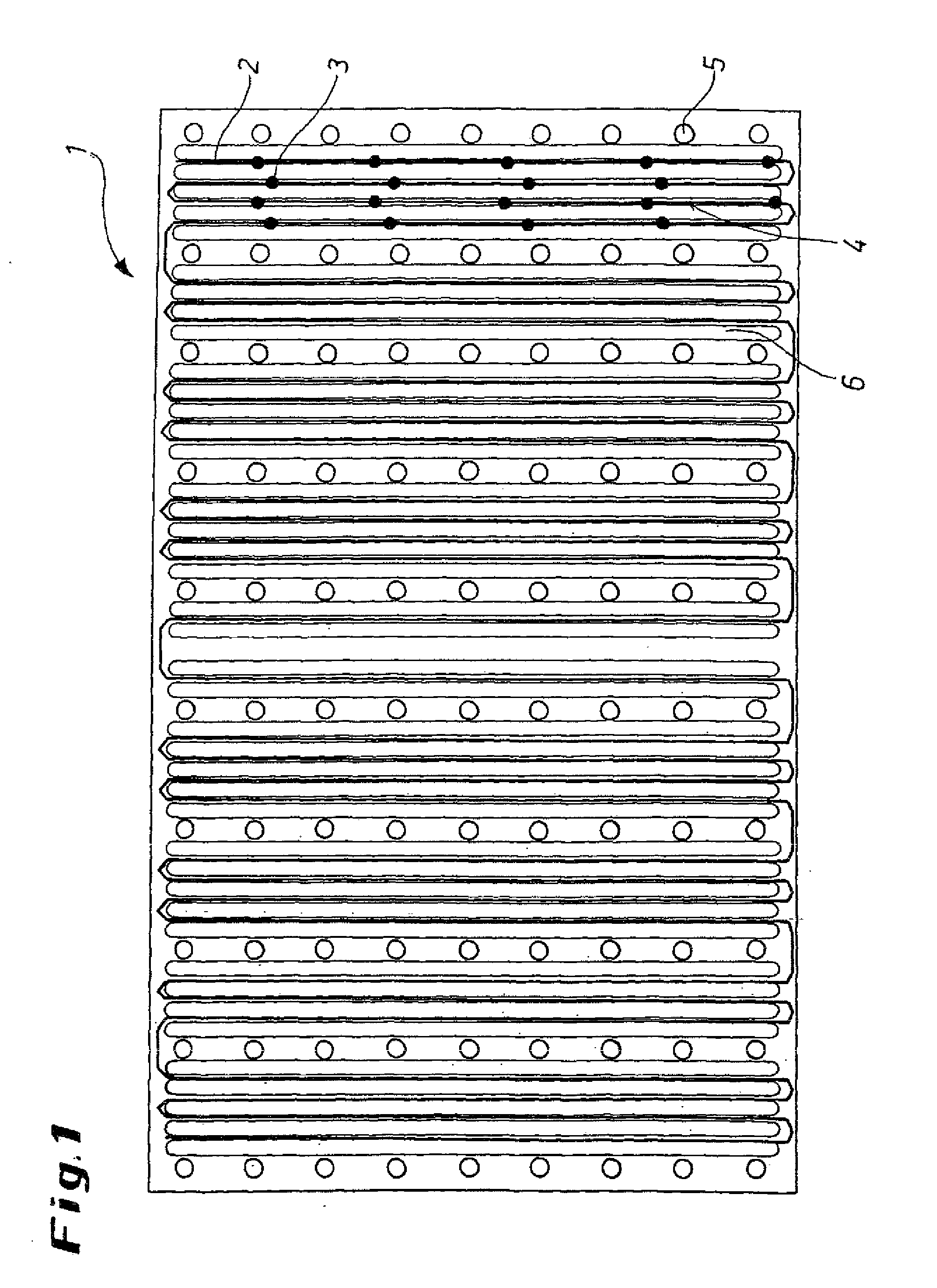
[0029]FIG. 1 shows an exemplary embodiment of the invention, in which a light waveguide fiber 2 is laid in meander fashion in grooves 4 between the cooling channels 6 on the rear surface of a copper plate 1 of a mold. In this exemplary embodiment, a light waveguide 2 containing only a few measuring sites 3 has been selected so that diagram can be understood more easily. Many more measuring sites 3 than this, of course, could also be provided. Necked-down bolts 5, in which thermocouples, for example, were or can be arranged, are also visible in this exemplary embodiment. In this exemplary embodiment, it can be seen that the resolution perpendicular to the casting direction is a multiple—perhaps double the resolution—of that obtainable with thermocouples installed exclusively in the necked-down bolts 5. As a result of this advantageous arrangement and use of light waveguide fibers 2, the occurrence of longitudinal cracks in particular can be monitored more effectively. Under certain c...


PUM

PropertyMeasurementUnit
diameteraaaaaaaaaa
diameteraaaaaaaaaa
sizeaaaaaaaaaa

Abstract

The invention presents a method for measuring the temperature in a mold by means of a fiber-optic measurement method and a correspondingly designed mold. For this purpose, light waveguides, through which laser light is conducted, are arranged in grooves in the outside surface of the copper mold plate. The temperature at several measurement points along the measurement fiber is determined by a temperature detection system. In particular, the method makes it possible to achieve much greater local resolution of the temperature measurements than that achieved by thermocouples.

Description

SCOPE OF THE INVENTION[0001]The invention pertains to a method for measuring the temperature in a mold by means of a fiber-optic measuring method and to a correspondingly designed mold. For this purpose, light waveguides, through which laser light is conducted, are provided on the outside surface of a mold. The invention serves to improve the local resolution of the temperature detection in a mold in comparison with the known temperature detection systems and makes it possible in particular to improve the detection of longitudinal cracks and fractures.PRIOR ART[0002]Temperature detection in a mold is a critical problem, which is becoming even more important in the case of casting machines operating at high speed. In most cases, temperatures in the mold are detected primarily by thermocouples, which are either guided through bores in the copper plate of the mold or welded onto the copper plates of the mold. Such measurement methods are based on the evaluation of thermal stresses. The...

Claims


Application Information

Patent Timeline
Patent Type & Authority Applications(United States)
IPC IPC(8): B22D46/00G01K11/32B22D2/00
CPCB22D2/006B22D11/202B22D11/182B22D2/00B22D11/18B22D11/20G01K11/32
Inventor ARZBERGER, MATTHIASLIEFTUCHT, DIRK
Owner SMS DEMAG AG
Why Eureka
Try Eureka