
Acoustic shield

Inactive Publication Date: 2011-06-16
BELLMAX ACOUSTIC
View PDF11 Cites 55 Cited by
  • Summary
  • Abstract
  • Description
  • Claims
  • Application Information

AI Technical Summary

Benefits of technology

[0012]In accordance with a first aspect of the present invention there is provided a multilayered acoustic shield for mounting to a panel of a vehicle. The shield includes an outer portion and an inner portion. The outer portion includes a support layer having apertures therein. The inner portion includes a sound absorbing layer and vibration dampening layer. The shield is fastenable to the panel of the vehicle such that at least a portion of the dampening layer engages the panel with the sound absorbing layer being compressed between the outer portion and the dampening layer, to thereby reduce the transmission of noise into a cabin of the vehicle.
[0017]In accordance with another aspect of the present invention there is provided a multilayered acoustic shield for mounting to an underside of a transmission tunnel in a vehicle floorpan. The shield includes an outer portion and an inner portion. The outer portion includes a support layer having apertures therein. The inner portion includes a sound absorbing layer and a vibration dampening layer, wherein the shield is fastenable to the vehicle floorpan such that at least a portion of the dampening layer engages with the underside of the transmission tunnel with the sound absorbing layer being compressed between the outer portion and the dampening layer, to thereby reduce the transmission of noise into a cabin of the vehicle.
[0018]The dampening layer is preferably made of a viscoelastic material which is moulded to conform with a curvature of the panel, for example the transmission tunnel. The sound absorbing layer in combination with the vibration dampening layer enables the present invention to provide an optimal degree of sound absorption. In this regard the vibration dampening material not only dampens the vibrational energy of sound waves within the transmission tunnel by directly contacting the transmission tunnel but also reduces the transmission of sound into the cabin of the vehicle due to an outer surface of the dampening material acting as a reflective surface to assist to deflect some of the airborne sound waves back into the sound absorbing layer. In addition, the vibration dampening material is able to absorb some of the airborne sound waves, which impact upon the outer surface, as mechanical energy.

Problems solved by technology

Vehicles such as automobiles, trains, buses, trucks, boats and the like typically produce significant levels of undesirable vibration and sound, otherwise known as noise.
The cabin of a vehicle, where the vehicle operator and / or passengers are located during transit, is subjected to varying degrees of external noise.
However, this approach has not always proved to be successful due to space constraints and harsh environmental conditions which can be experienced externally of the cabin, for example underneath the vehicle's floorpan.
A problem with using acoustic shielding inside the vehicle's cabin is that the shielding takes up interior space as it needs to be particularly thick to provide a similar level of performance to external shielding.
Unfortunately, as the stiffness of a vehicle's body increases so to does the transmission of noise and vibration through the body.
A problem with applying vibration dampening material this way is that molten dampening material can flow on vertical or inclined surfaces and thereby gather in certain areas which results in the material having an uneven thickness over the floorpan.
However, the engine bay and area underneath the floorpan of the cabin are harsh environments for acoustic material as significant heat is generated by the engine, transmission and exhaust system in these areas.
The exterior of an exhaust system's muffler and connecting pipes can typically reach temperatures of 500° C. Such extreme heat can result in the floorpan reaching temperatures in excess of 220° C. Further, these areas, particularly the underside of the floorpan, are usually subjected to water, dirt, rocks and other debris.
Unfortunately, a problem with this type of arrangement is that the shield may be excited by structural vibrations within the floorpan which can result in the shield generating noise in excess of 3 dB.
A further problem with this type of arrangement is that the protective metal cover can have a detrimental impact upon the acoustic performance of the shield.
In this respect, the metal cover has a tendency to reflect noise incident on the shield rather than allow noise to penetrate and thereby interact with the inner layers of the shield.

Method used


Image

  • Acoustic shield
  • Acoustic shield
  • Acoustic shield

Examples


Embodiment Construction

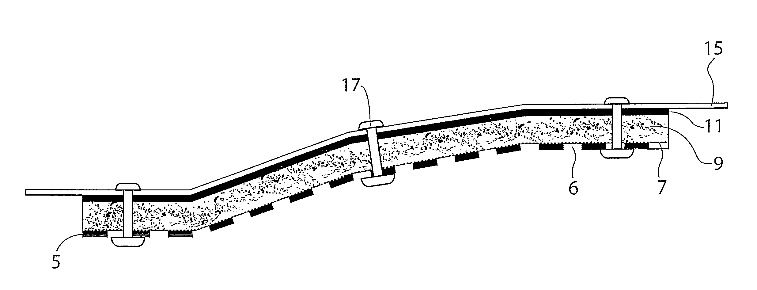
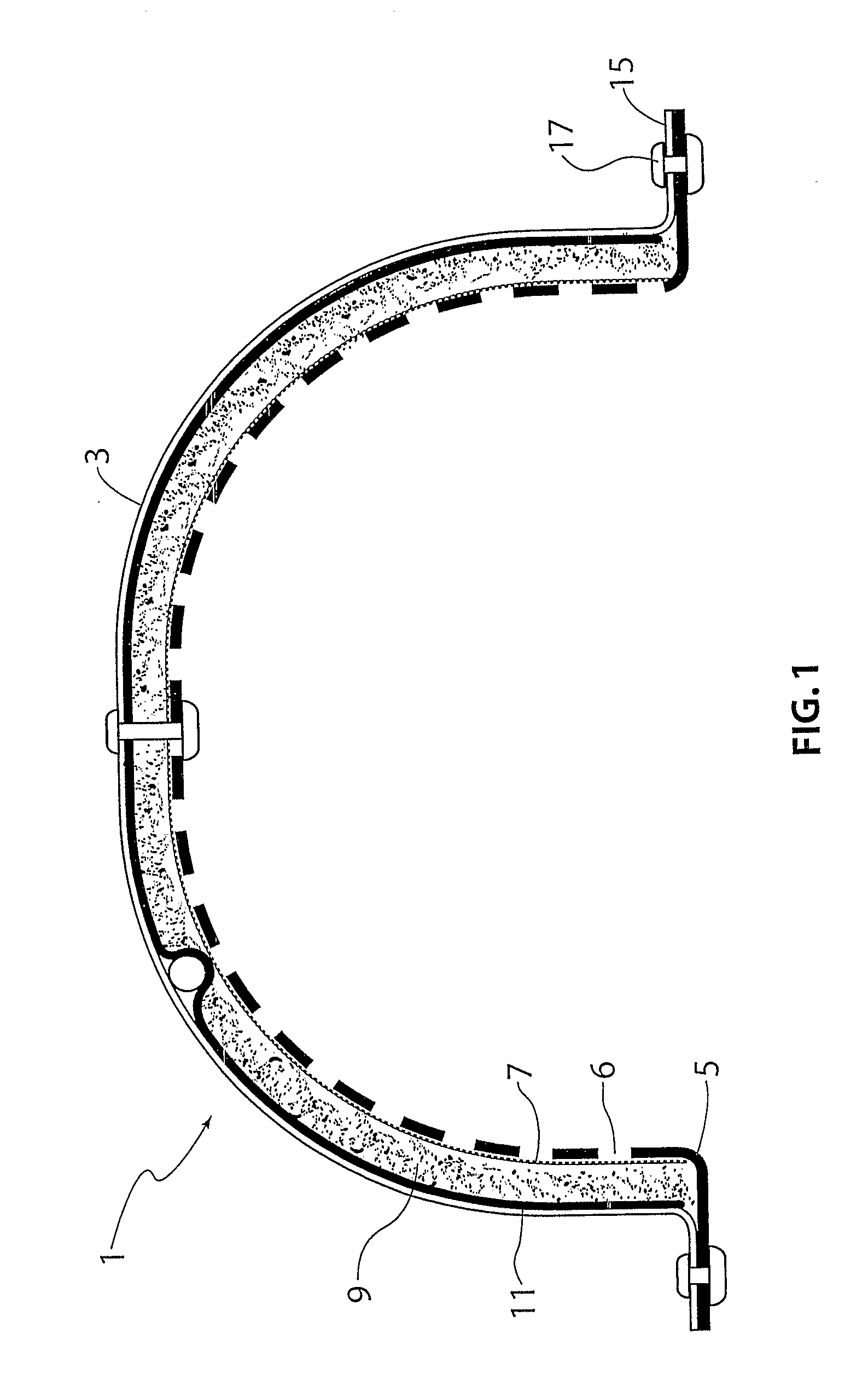
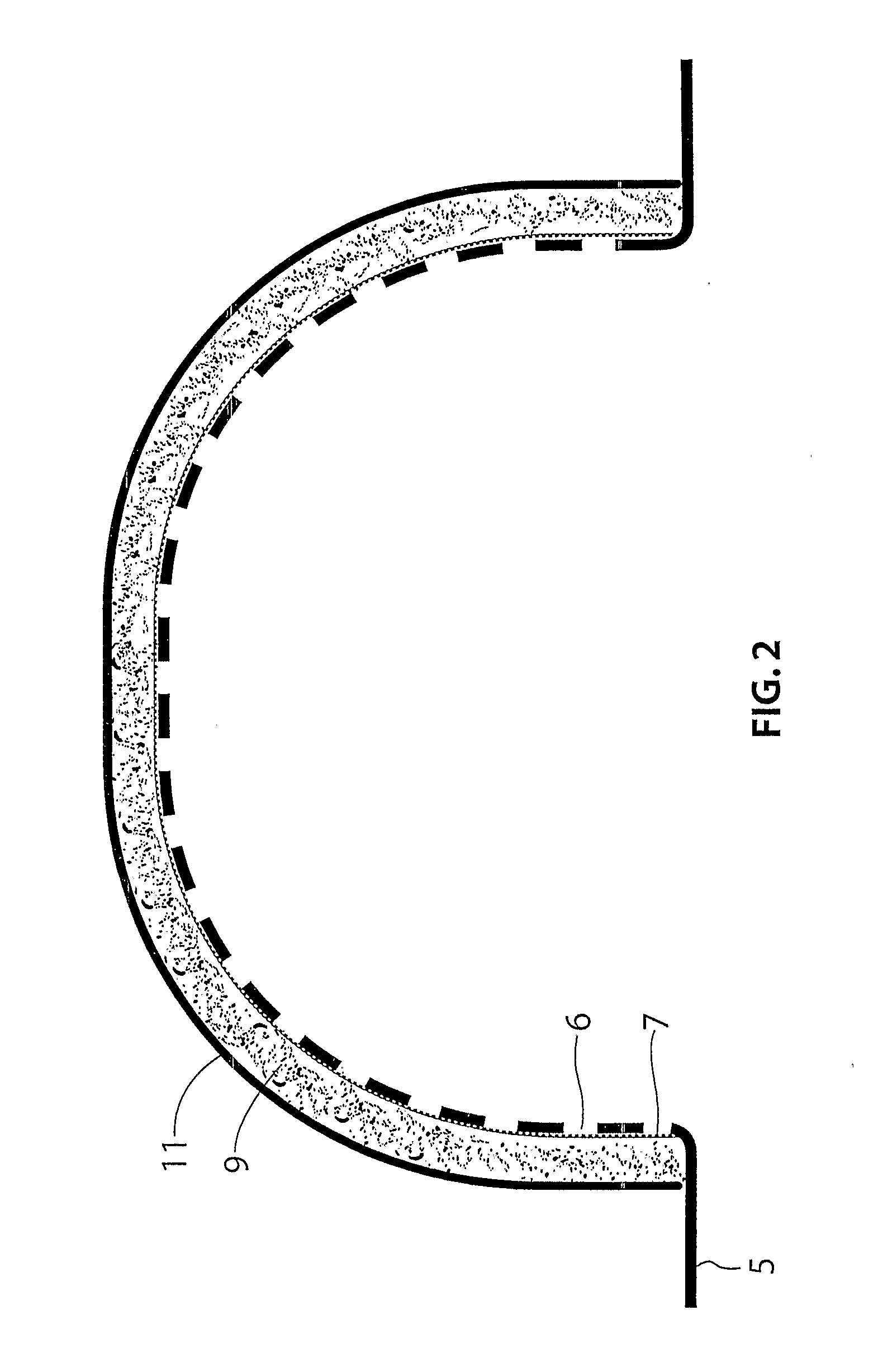
[0037]With reference to FIG. 1 of the accompanying drawings there is shown a multilayered acoustic shield 1 mounted to the underside of a transmission tunnel 3 in a vehicle floorpan 15. The shield 1 includes an outer portion and an inner portion. The outer portion includes a support layer 5 having a series of apertures 6. The support layer 5 is preferably made of a sheet of rigid material. The outer portion may also further include a metallic foil 7 which can have perforations therein. The inner portion includes a sound absorbing layer 9 and a vibration dampening layer 11. The support layer 5 is preferably a sheet material that is rigid and made of metal, for example aluminium. The metal preferably has a thickness of between approximately 0.4 mm and 2 mm.

[0038]The support layer 5 is the main structural layer of the shield 1 and in part functions to protect the underlying layers from the surrounding environment. For example, the support layer 5 can protect the underlying layers from ...


PUM

PropertyMeasurementUnit
Metallic bondaaaaaaaaaa
Viscoelasticityaaaaaaaaaa

Abstract

A multilayered acoustic shield (1) for mounting to a panel of a vehicle, the shield (1) including an outer portion and an inner portion, the outer portion including a support layer (5) having apertures (6) therein, the inner portion including a sound-absorbing layer (9) and a vibration-dampening layer (11), wherein the shield (1) is fastenable to the panel of the vehicle such that at least a portion of the dampening layer (11) engages the panel with the sound-absorbing layer (9) being compressed between the outer portion and the dampening layer (11), to thereby reduce the transmission of noise into a cabin of the vehicle.

Description

FIELD OF THE INVENTION[0001]The present invention relates to an acoustic shield. More particularly, the invention relates to a multilayered acoustic shield. As the acoustic shield is particularly suited for mounting to a vehicle, in particular the transmission tunnel of an automobile, it will be convenient to describe the invention in relation to that example application. It should however be understood that the invention is equally suitable for mounting to other parts of a vehicle—for example, a firewall in the engine bay of the vehicle. Further it should be understood that the invention is also intended for other applications besides vehicles.BACKGROUND OF THE INVENTION[0002]Vehicles such as automobiles, trains, buses, trucks, boats and the like typically produce significant levels of undesirable vibration and sound, otherwise known as noise. The cabin of a vehicle, where the vehicle operator and / or passengers are located during transit, is subjected to varying degrees of external...

Claims


Application Information

Patent Timeline
IPC IPC(8): G10K11/168E04B1/82B32B7/022
CPCB32B3/266B32B2605/003B32B15/08B60R13/0861B60R13/0876B60R13/0884B32B5/022B32B11/00B32B11/10B32B15/14B32B15/20B32B25/10B32B27/12B32B27/306B32B3/00B32B2262/0276B32B2307/102B32B2307/51B32B2307/56B32B2307/718B32B7/02B32B7/022G10K11/168
Inventor BORRONI, MARK
Owner BELLMAX ACOUSTIC
Learn More