Ceramic exhaust gas sensor

Inactive Publication Date: 2011-06-16
DELPHI TECH INC
View PDF10 Cites 26 Cited by
  • Summary
  • Abstract
  • Description
  • Claims
  • Application Information

AI Technical Summary

Benefits of technology

[0022]Ceramic exhaust gas sensors according to the present invention offer enhanced dimensional stability during curing, with redu

Problems solved by technology

During this sintering process, the sensing element may be subject to undesirable ph

Method used


Image

  • Ceramic exhaust gas sensor
  • Ceramic exhaust gas sensor
  • Ceramic exhaust gas sensor

Examples


examples

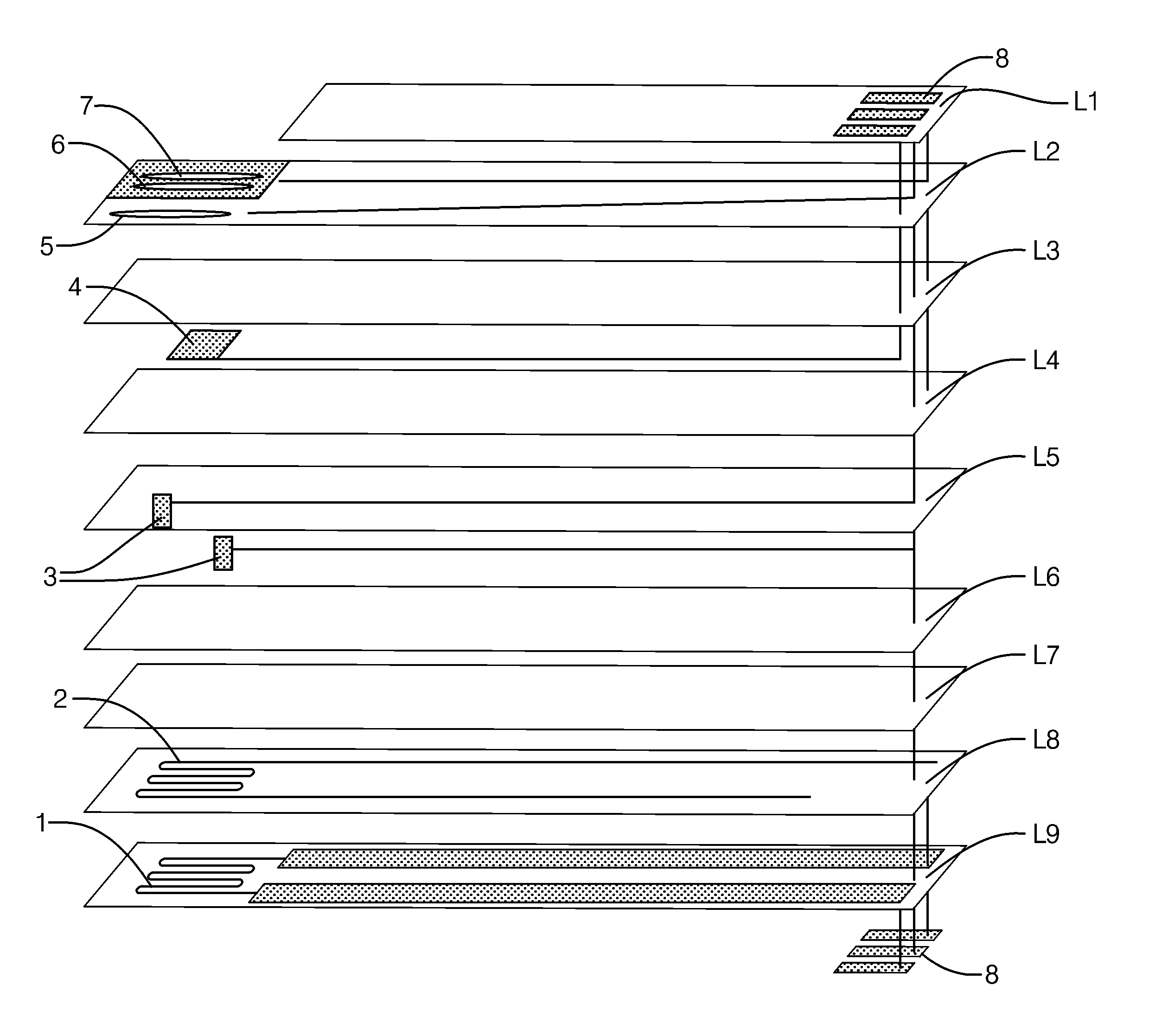
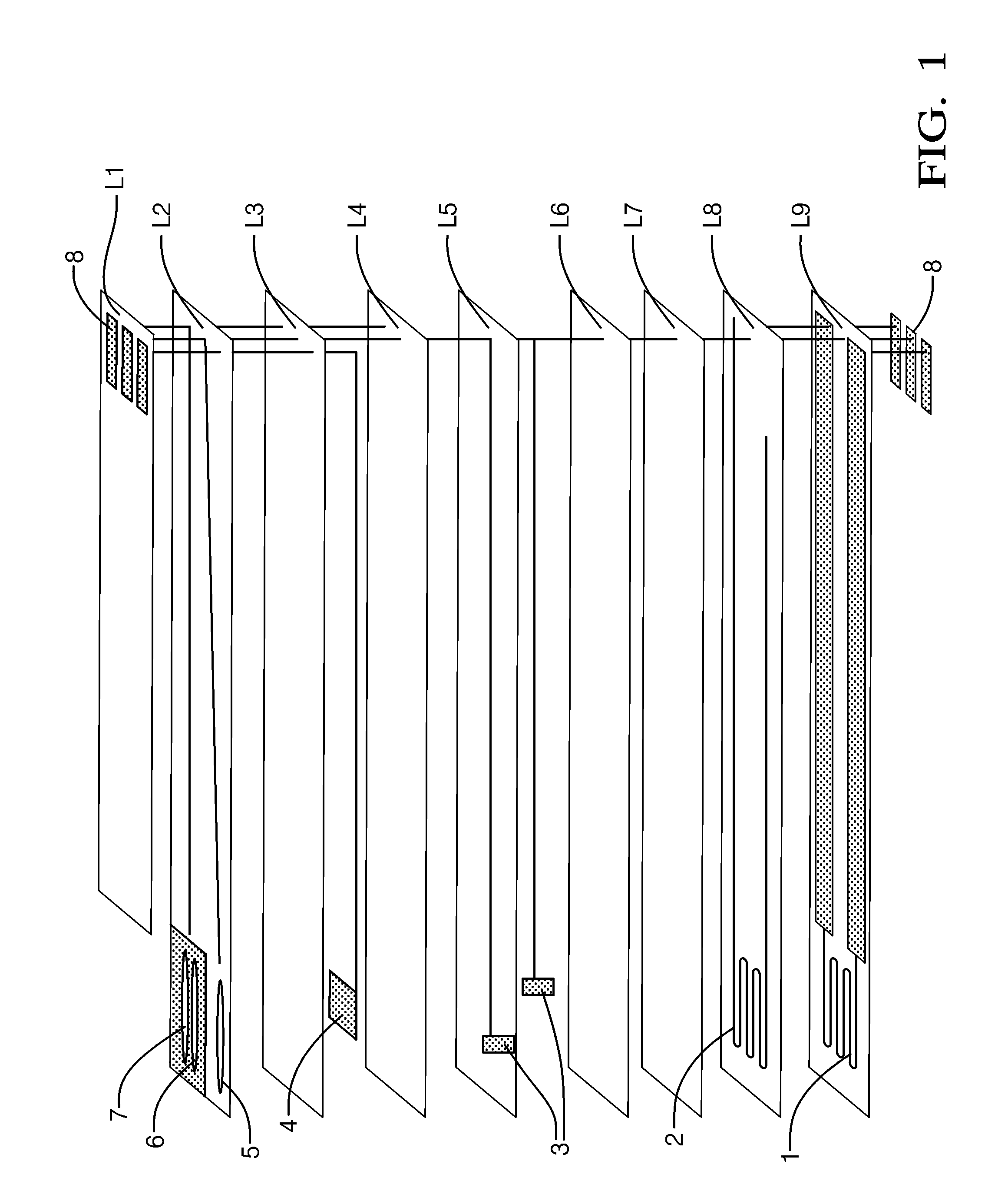
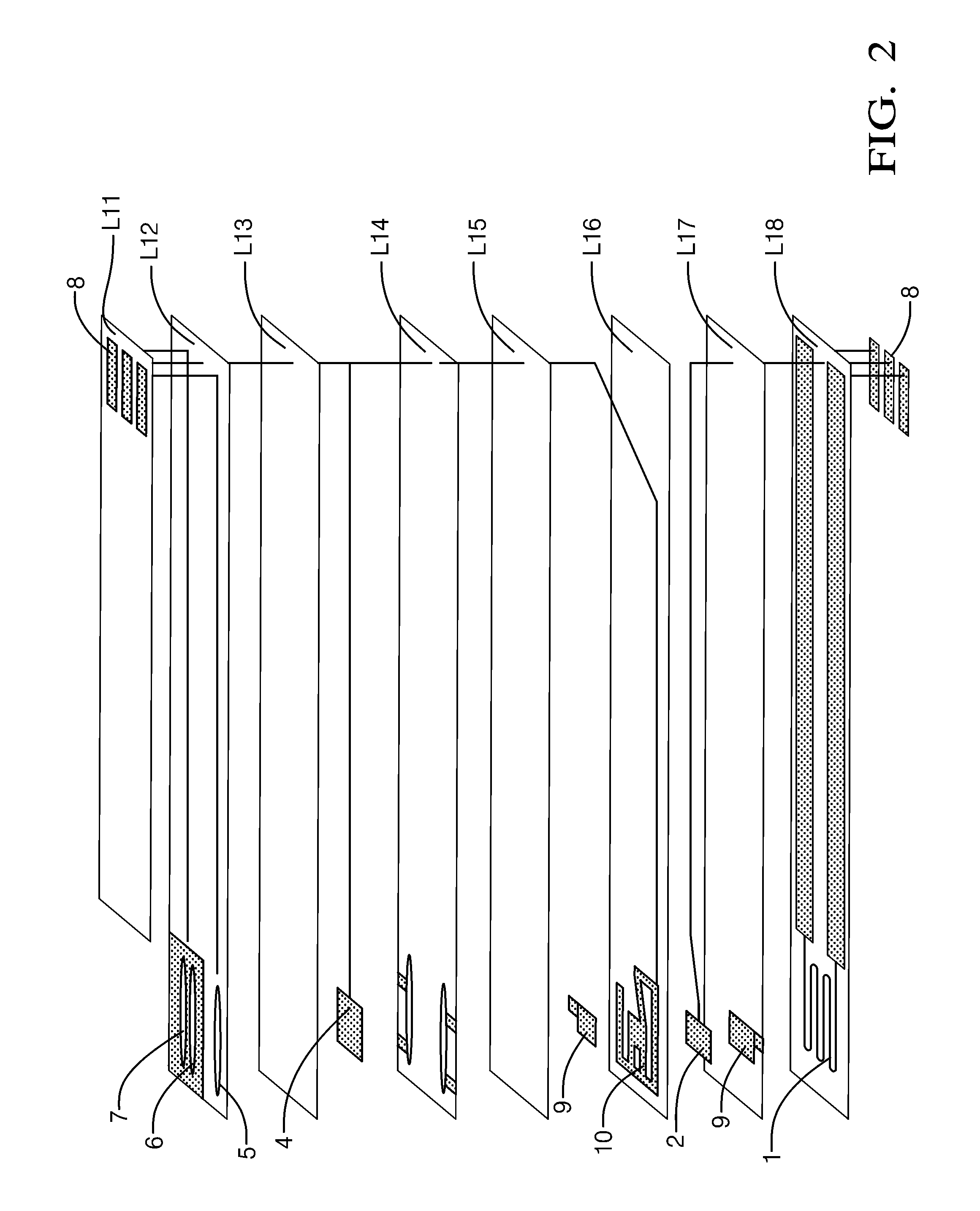
[0064]Sensor elements with the structures shown in FIGS. 14 and 2 were prepared from tape and ink raw materials. For each design, the appropriate number and thickness of tape cast alumina and zirconia tapes were blanked into sheets sized for producing seven elements in an array pattern. Via holes and electrode holes were punched into the sheet layers. The conductive circuits were applied to the sheets by screen printing platinum inks onto them. Fugitive carbon inks were printed for forming the chamber and channel features. For each design, the sheets were stacked in the correct order and orientation on a metal plate, sealed in an evacuated plastic bag, and laminated together in an isostatic laminator. Individual green ceramic elements were cut from the laminated tiles using a hot-knife. The organic binder and fugitive carbon material were burned away during a controlled temperature ramp up to a 120 minute hold at a sintering temperature of 1435° C. in a high temperature kiln. FIG. 1...


PUM


Abstract

Ceramic exhaust gas sensors are disclosed that offer enhanced dimensional stability during curing, with reduced occurrence of deformations like bending or warping, and can be used in a variety of exhaust gas component sensing applications. The sensors of the invention utilize appropriate selection and orientation of the various layers of green ceramic tape that make up the sensor structure to provide enhanced dimensional stability.

Description

BACKGROUND OF THE INVENTION[0001]This invention relates to sensors used to detect various constituents (e.g., oxygen, ammonia, hydrogen, nitrogen oxides, carbon monoxide, hydrocarbons, etc.) in combustion exhaust, such as the exhaust from internal combustion engines. Such sensors often include a flat or planar sensing element having multiple ceramic layers that provide for fluid flow on and through the sensor element and on which are disposed various components such as sensing electrodes, ground or reference electrodes, resistors, heater elements, and the like used to detect constituents of interest. Planar ceramic sensor elements are often manufactured by forming a multilayer element of layers of uncured ceramic material known as ceramic tape using known ceramic tape casting methods. Alternative methods may also be used, such as die pressing, roll compaction, stenciling, screen printing and the like. Electrodes and similar components may be disposed onto any of the various layers o...

Claims


Application Information

Patent Timeline
IPC IPC(8): G01N27/407
CPCG01N27/4071G01N33/0054G01N33/0037Y02A50/20
Inventor SERRELS, DANA M.BLOINK, RAY L.
Owner DELPHI TECH INC
Why Eureka
Try Eureka