
Continuous Critical Current Measurement Apparatus And Method Of Measuring Continuous Critical Current Using The Same

a technology of critical current and measurement apparatus, which is applied in the direction of superconducting properties measurement, instruments, magnetic properties, etc., can solve the problems of low strength, unsuitable method for measuring the critical current of a long tape, and easy burnout of superconducting tap

Active Publication Date: 2011-06-16
KOREA ELECTROTECH RES INST
View PDF6 Cites 4 Cited by
  • Summary
  • Abstract
  • Description
  • Claims
  • Application Information

AI Technical Summary

Benefits of technology

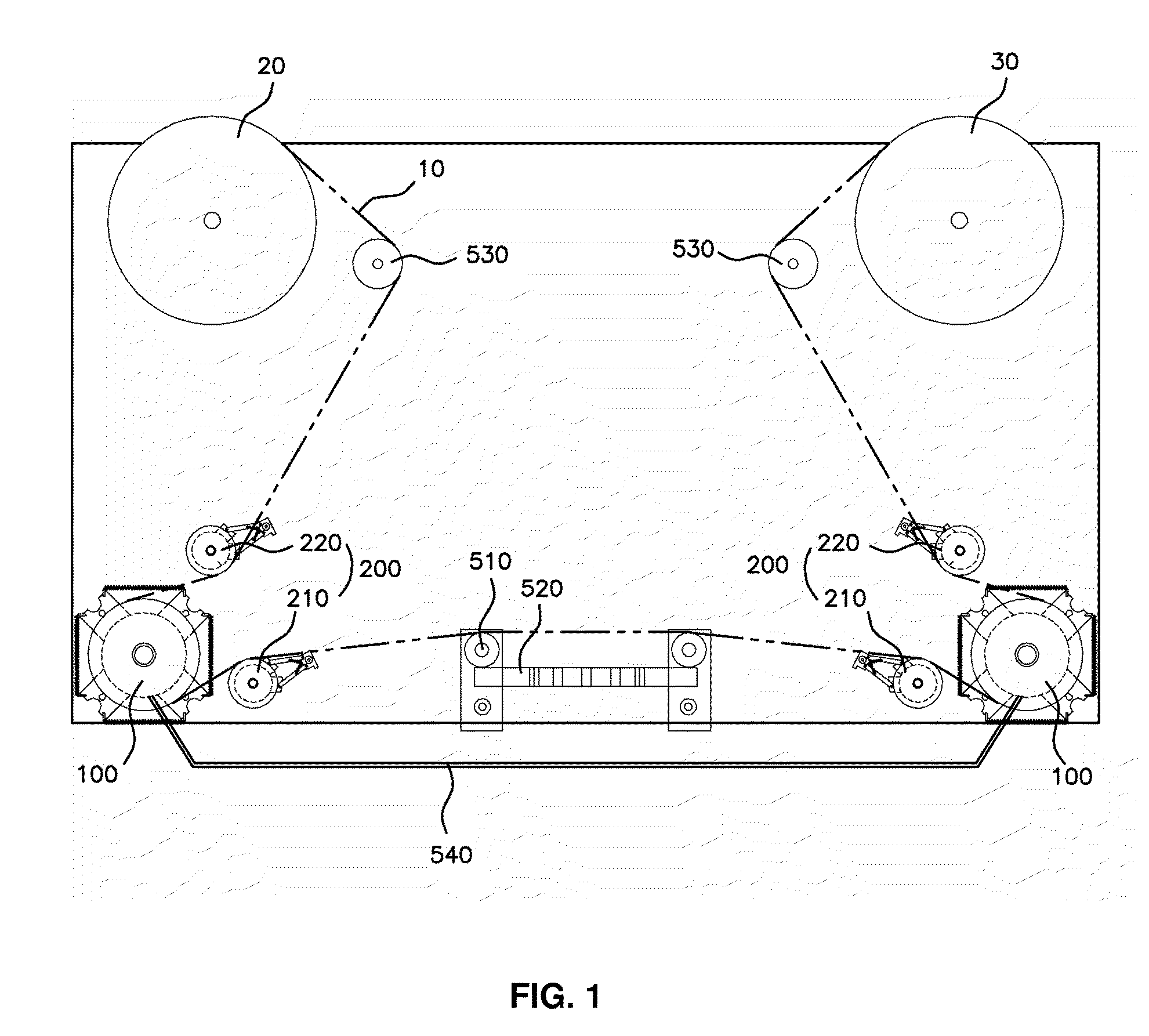
[0015]Accordingly, the present invention has been made keeping in mind the above problems occurring in the prior art, and an object of the present invention is to provide a continuous critical current measurement apparatus, which can continuously measure the critical current of a superconducting tape using wheel-type current and voltage terminals without burning out the superconducting tape while continuously supplying the superconducting tape using a reel-to-reel device.
[0017]A further object of the present invention is to provide a continuous critical current measurement method, which measures current, required to control voltage of a superconducting tape at 0.1 mV per meter while moving the superconducting tape at regular time intervals by using the continuous critical current measurement apparatus, as critical current, thus shortening the time required for the measurement of the critical current and accurately measuring the critical current.

Problems solved by technology

However, such a method is disadvantageous in that a superconducting tape may easily burn out due to overcurrent occurring during the measuring of critical current, a load applied to the tape on account of current and voltage terminals, and a soldering operation performed when the terminals for measurement are formed.
Further, such a method is unsuitable for measuring the critical current of a long tape.
However, since high-temperature superconducting tapes which have been developed to date use silver (Ag) or an alloy of silver as the outer surfaces thereof, they are of low strength.
Therefore, due to the low-strength characteristics of superconducting tapes, it is almost impossible to use a continuous critical current measurement apparatus, and thus a batch-type critical current measurement apparatus must be used.
That is, during a procedure for applying pressure to ensure a sufficiently large contact area in the current terminals for current conduction, a superconducting tape may burn out due to overpressure.
Further, when the pressure is excessively low, measurement errors occur due to contact resistance when the current is conducted.
Further, similarly to the voltage terminal, when applied pressure is excessively low, noise may occur during voltage measurement, whereas when applied pressure is excessively high, burning out of the superconducting tape may be caused.
Those related arts do not disclose the measurement of continuous critical current in the strict sense.
If a long superconducting tape is measured, an operation of raising and lowering a current or voltage terminal must be repeated in such a go-and-stop manner, and thus there is a disadvantage in that a lot of time is required for the measurement of critical current especially for a long superconducting tape.
Further, those patents are problematic in that, since average critical current is measured, local defects cannot be found, so that the characteristics of a superconducting tape are not properly evaluated, and measurement resolution is limited.
Furthermore, in the case of technology disclosed in U.S. Pat. No. 7,554,317B2, since a current terminal is formed to be of a wheel type, current can be continuously applied, but a voltage terminal is not formed to be of a wheel type, thus making it impossible to properly perform continuous processing.
Furthermore, the conventional schemes are disadvantageous in that the force of contact between the superconducting tape and the current and voltage terminals decreases, thus increasing contact resistance, and in that it is impossible to measure voltage between current and voltage terminals, thus making it difficult to measure critical currents on all areas of the superconducting tape.

Method used


Image

  • Continuous Critical Current Measurement Apparatus And Method Of Measuring Continuous Critical Current Using The Same
  • Continuous Critical Current Measurement Apparatus And Method Of Measuring Continuous Critical Current Using The Same
  • Continuous Critical Current Measurement Apparatus And Method Of Measuring Continuous Critical Current Using The Same

Examples


Embodiment Construction

[0040]Hereinafter, embodiments of an apparatus for measuring the critical current of a superconducting tape according to the present invention will be described in detail with reference to the attached drawings.

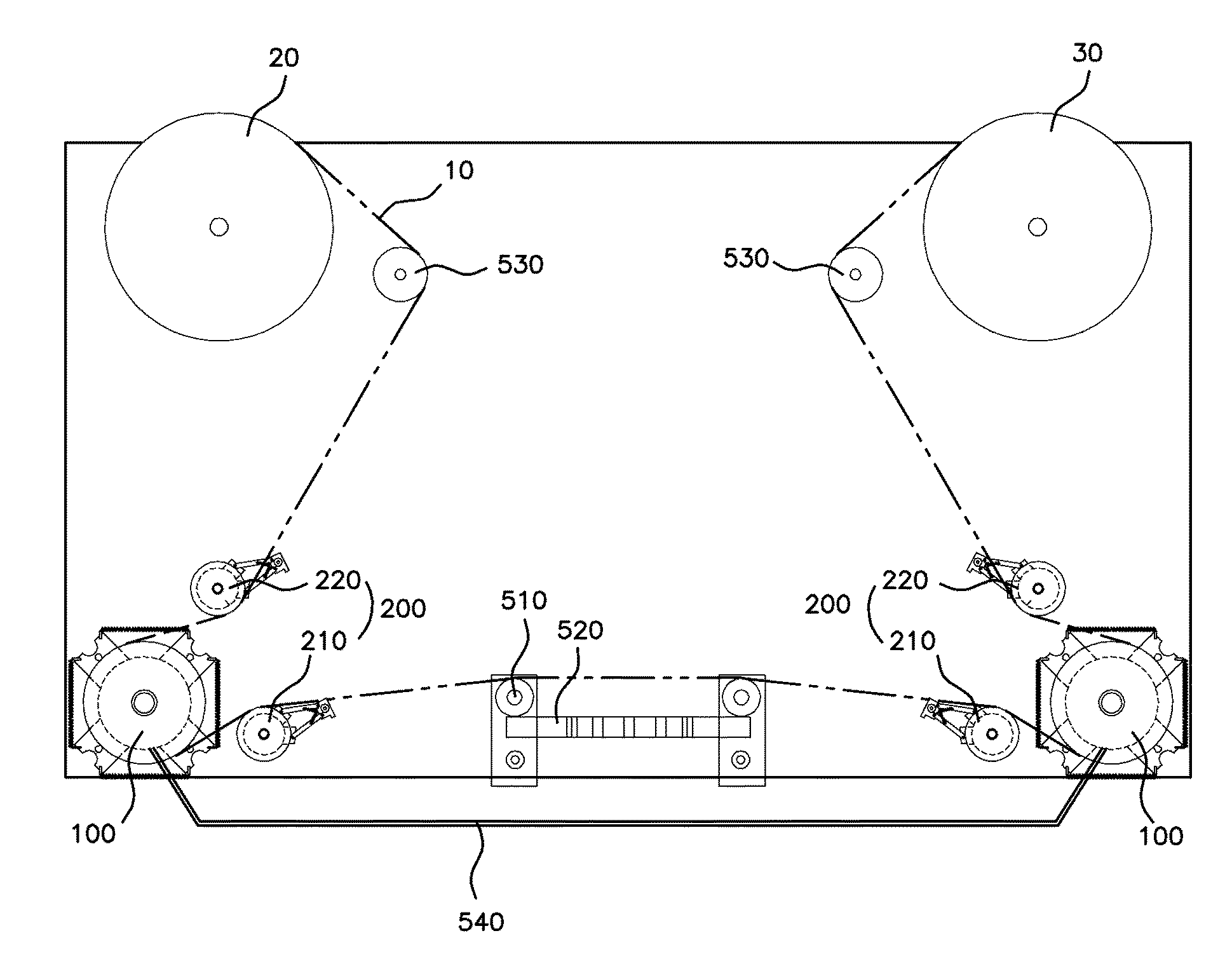
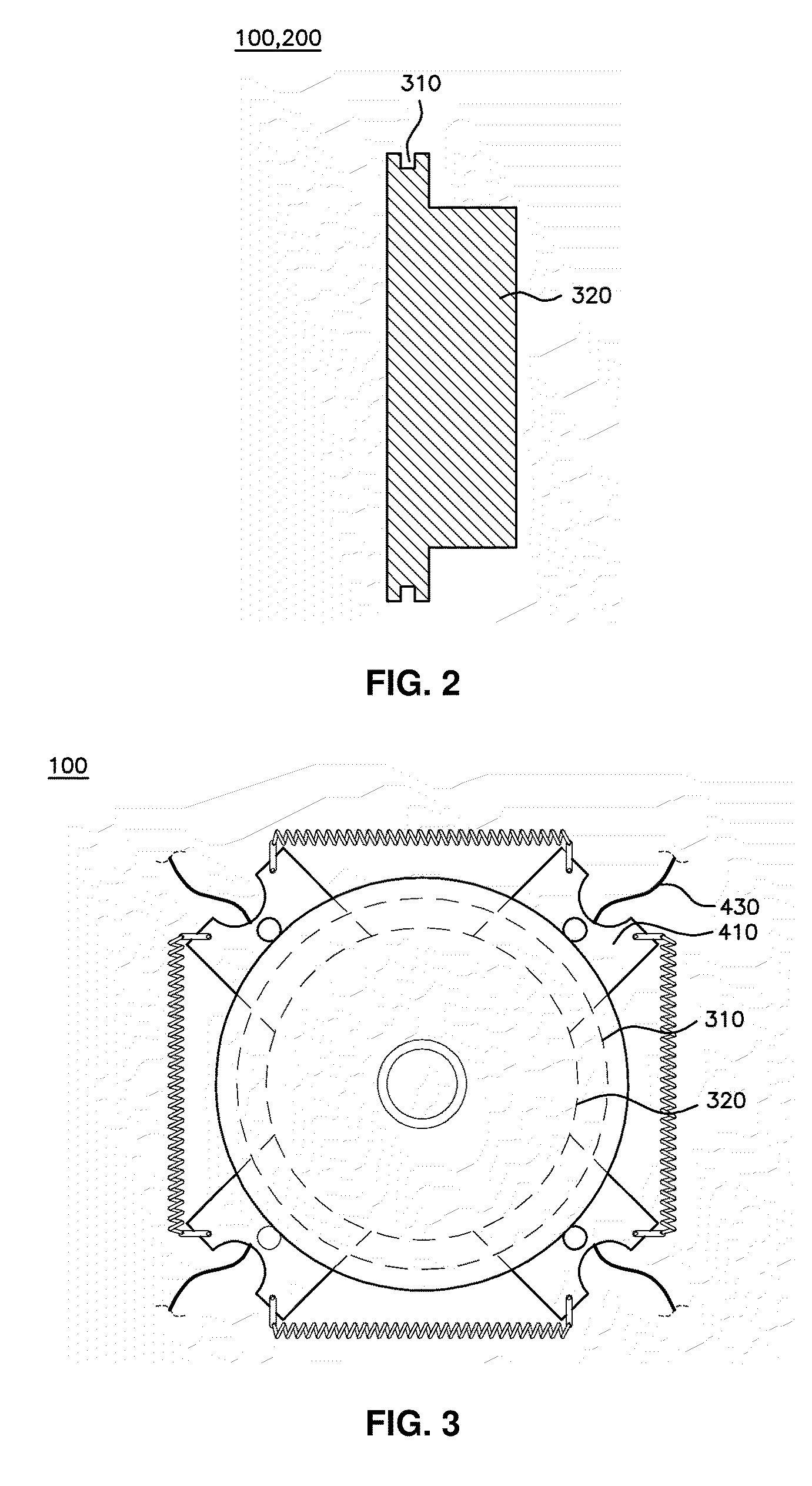
[0041]FIG. 1 is a diagram showing the construction of principal components of a continuous critical current measurement apparatus according to the present invention, FIG. 2 is a sectional view of the current terminal or voltage terminal of the continuous critical current measurement apparatus according to the present invention, FIG. 3 is a diagram showing the brush-type current lead-in structure or brush-type voltage measurement structure of the continuous critical current measurement apparatus according to an embodiment of the present invention, FIG. 4 is a diagram showing the brush-type current lead-in structure or brush-type voltage measurement structure of the continuous critical current measurement apparatus according to another embodiment of the present invention, and F...


PUM


Abstract

The present invention relates to an apparatus and method for measuring the critical current of a superconducting tape. A continuous critical current measurement apparatus for measuring critical current of a superconducting tape while feeding a superconducting tape in a liquid nitrogen container includes wheel-type current terminals and wheel-type voltage terminals. The superconducting tape is continuously supplied and fed by a reel-to-reel device, and the critical current of the superconducting tape is measured in real time using the wheel-type current terminals and the wheel-type voltage terminals while the superconducting tape is fed at constant linear velocity in contact with the wheel-type current terminals and the wheel-type voltage terminals.Accordingly, current is applied using wheel-type current terminals and voltage is measured using wheel-type voltage terminals while a superconducting tape is continuously supplied by a reel-to-reel device, thus continuously measuring critical current without burning out the superconducting tape.

Description

FIELD OF THE INVENTION[0001]The present invention relates, in general, to an apparatus for measuring the critical current of a superconducting tape, and, more particularly, to a continuous critical current measurement apparatus, which can continuously measure the critical current of a superconducting tape using wheel-type current and voltage terminals without burning out the superconducting tape while continuously supplying the superconducting tape using a reel-to-reel device.[0002]Further, the present invention relates to a method of continuously measuring the critical current of a superconducting tape, which measures the current, required to control the voltage of a superconducting tape at 0.1 mV per meter, as critical current by moving the superconducting tape at regular time intervals using a continuous critical current measurement apparatus, thus reducing the time required for the measurement of critical current and accurately measuring the critical current.BACKGROUND OF THE IN...

Claims


Application Information

Patent Timeline
IPC IPC(8): G01R31/02
CPCG01R33/1246G01N27/00G01R19/00
Inventor HA, HONG-SOOKIM, SEOK-HOSIM, KI-DEOKOH, SANG-SOOPARK, MIN-WON
Owner KOREA ELECTROTECH RES INST
Learn More