Dc-link voltage balancing system and method for multilevel converters

a multi-level converter and dc-link technology, applied in power conversion systems, emergency protective circuit arrangements, electrical equipment, etc., can solve problems such as voltage and under voltage trips during the operation of the converter, increase in output voltage total harmonic distortion (thd), and control loop instability

Active Publication Date: 2011-06-16
GENERAL ELECTRIC CO
View PDF9 Cites 85 Cited by
  • Summary
  • Abstract
  • Description
  • Claims
  • Application Information

AI Technical Summary

Benefits of technology

[0006]In accordance with an embodiment of the present invention, a control system for controlling a multilevel converter is provided. The control system includes a differential mode current regulator to generate reference voltage command signals based on a difference between reference current command signals and actual current command signals. The system also includes a neutral point (NP) controller to determine a modified neutral point current signal in response to a DC link voltage unbalance and to use the modified neutral point current signal to generate a common mode reference voltage signal. The system further includes a PWM controller to generate switching pulses for the multilevel converter based on the reference voltage command signals and the common mode reference voltage signals.

Problems solved by technology

DC link voltage balancing is a challenge when operating three level neutral clamped converters (NPC).
DC link voltage unbalance may overstress the capacitors and switching devices and cause over voltage and under voltage trips during the operation of the converter.
DC link voltage unbalance also causes an increase in output voltage total harmonic distortion (THD) and may cause the control loop to become unstable.
This method, however, includes additional expense, does not compensate for steady-error in DC link voltage, and also results in high THD in the output voltage and injects active 2nd harmonic current at AC side.
However, this method also has high THD in the output voltage at some operation points and becomes unstable at low power factors.

Method used


Image

  • Dc-link voltage balancing system and method for multilevel converters
  • Dc-link voltage balancing system and method for multilevel converters
  • Dc-link voltage balancing system and method for multilevel converters

Examples


Embodiment Construction

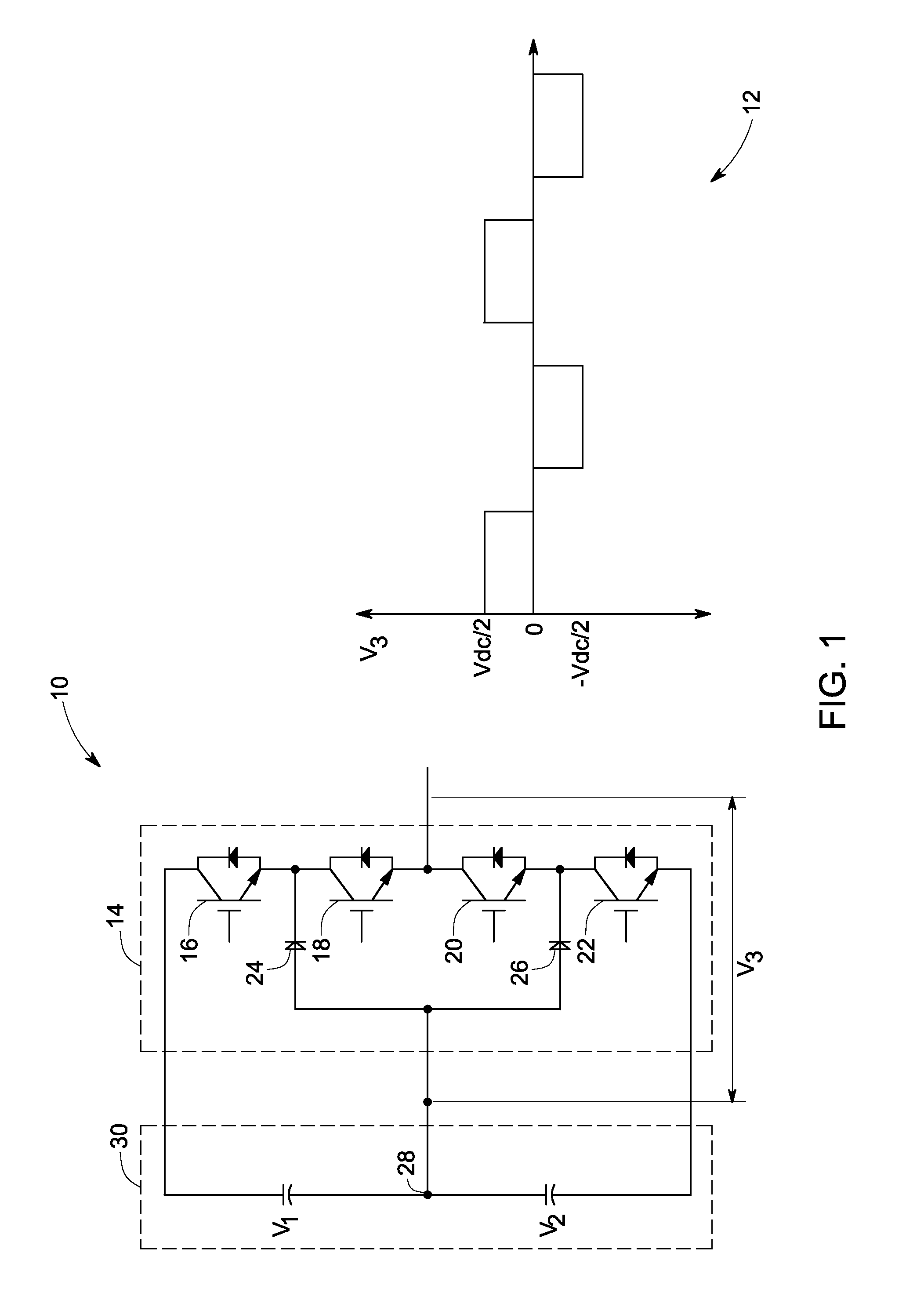
[0018]FIG. 1 illustrates a schematic 10 of one leg or one phase of a conventional neutral point clamped (NPC) or diode clamped three level converter and its output waveform 12. One leg 14 of the three-level converter includes four switching devices 16, 18, 20, and 22 and two clamping diodes 24 and 26. Input voltages V1 and V2 are controlled to each have a voltage equal to Vdc / 2, where Vdc is the total DC link voltage. Voltage V3 is the phase A output voltage measured with respect to a center point or a neutral point 28 of DC link 30. Switching device 16 is complementary to switching device 20 so that, when switching device 16 is gated on, switching device 20 is gated off and vice versa. Similarly, switching devices 18 and 22 are complementary.

[0019]In operation, each leg of the NPC three level converter has three switching stages P, O, and N respectively. The three switching stages and the respective output voltages are given in following table:

TABLE 1SwitchingSwitchingSwitchingSwit...


PUM


Abstract

A control system for a multilevel converter includes a differential mode current regulator, a neutral point (NP) controller and a PWM controller for generating switching pulses for the multilevel converter. The differential mode current regulator generates reference voltage command signals based on a difference between reference current command signals and actual current command signals, and the NP controller determines a modified neutral point current signal in response to a DC link voltage unbalance. The NP controller utilizes the modified neutral point current signal to generate a common mode reference voltage signal. The switching pulses are generated by the PWM controller based on the reference voltage command signals and the common mode reference voltage signal.

Description

BACKGROUND[0001]This invention relates to multilevel converters and more specifically to a system and method for DC link voltage balancing in multilevel converters.[0002]Multilevel converters are generally used in high power industrial applications such as variable speed drive (VSD) systems or in energy conversion applications such as a solar (or photovoltaic) power generation systems, wind turbine generators and marine and hydrokinetic power generation systems. One example of a multi-level converter is a neutral point clamped (NPC) converter. A three level converter, for example, typically includes two capacitor voltages in series with a center tap as the neutral and two phase legs each comprising two pairs of switching devices in series. In one embodiment, each switching device comprises an anti-parallel connection of a unidirectional electronic switching device, such as an insulated gate bipolar transistor or an insulated gate commutated thyristor, and a diode, such as a free-whe...

Claims


Application Information

Patent Timeline
Patent Type & Authority Applications(United States)
IPC IPC(8): H02M7/537
CPCH02M2001/123H02M7/487H02M1/0025
Inventor SHEN, JIESCHROEDER, STEFANROESNER, ROBERT
Owner GENERAL ELECTRIC CO
Why Eureka
Try Eureka