Flexible Screw

a screw and flexible technology, applied in the field of flexible screws, can solve the problems of limited flexibility in all directions, and achieve the effects of increasing the flexibility of the component, increasing the width, and limited flexibility

Inactive Publication Date: 2011-06-16
FLEX TECH
View PDF21 Cites 246 Cited by
  • Summary
  • Abstract
  • Description
  • Claims
  • Application Information

AI Technical Summary

Benefits of technology

[0017]A plurality of slots can be employed thereby increasing the flexibility of the component, relative to a shaft having a single slot of identical pattern. The serpentine path forms a plurality of teeth and complimentary recesses on opposite sides of the slot. The slot has sufficient width to form an unbound joint permitting limited movement in any direction between the teeth and the recesses, thereby providing limited flexibility in all directions upon application of tensile, compressive, and/or torsion forces to said component. In a similar manner the slot can have increased width in one direction compared to another direction thus providing increased flexibility in one direction.
[0018]The flexible segment can have different degrees of flexibility along the length of said shaft. The varied flexibility can be achieved b

Problems solved by technology

The slot has sufficient width to form an unbound joint permitting limited movement in any direction between the teeth and the recesses, t

Method used


Image

  • Flexible Screw
  • Flexible Screw
  • Flexible Screw

Examples


Embodiment Construction

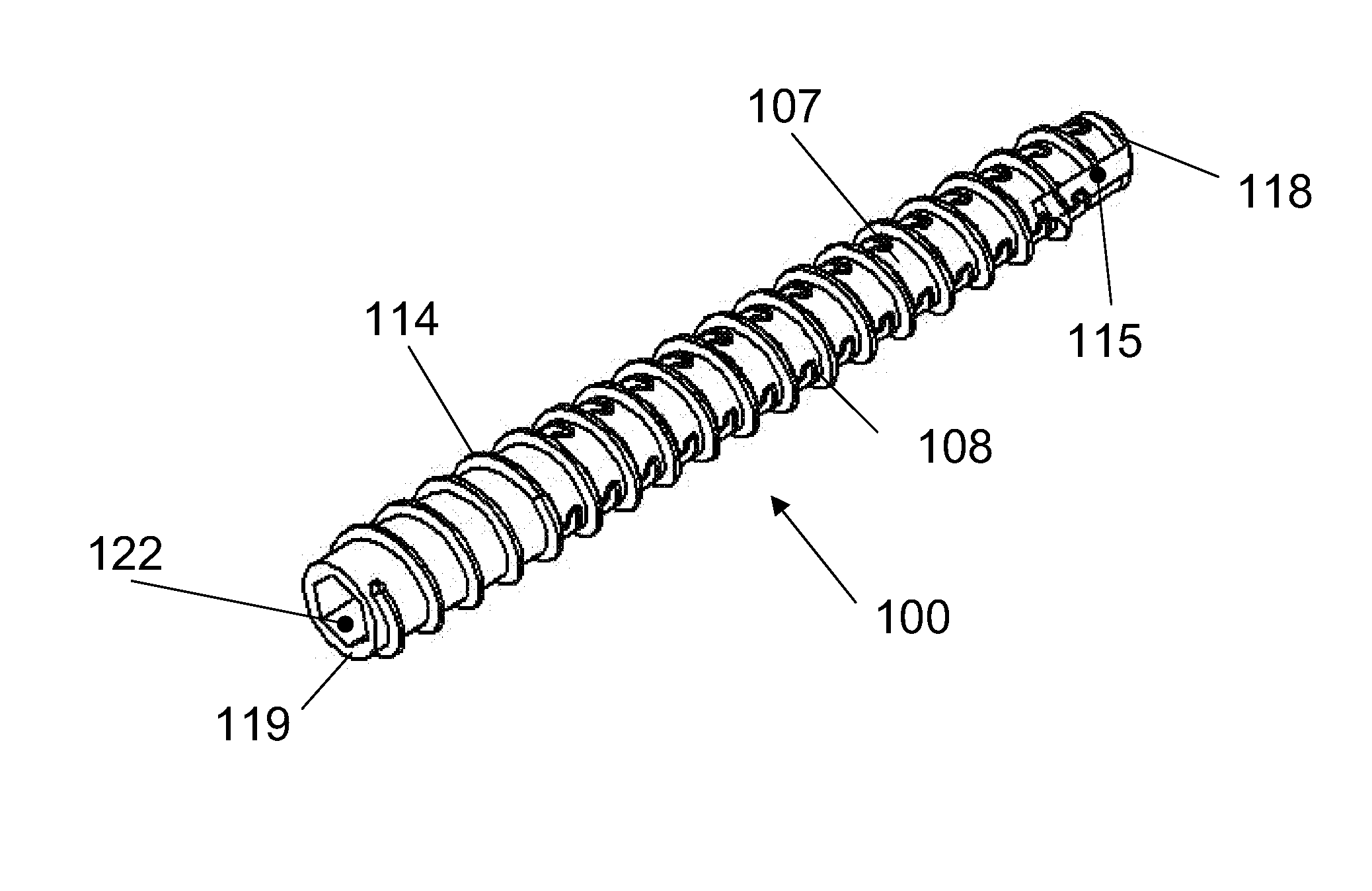
ional view of the central segment through the longitudinal axis of FIG. 20, showing general pattern of the offset serpentine, circumferential slots along the length of the segment in accordance with the invention;

[0048]FIG. 22 is an exploded view of section 21 showing the gap and interlocking of the serpentine slot of two slots that have been offset or staggered;

[0049]FIG. 23 is a schematic representation of the central segment of FIG. 18, showing general pattern of the circumferential serpentine slots with an elastomer filler material in the slot;

[0050]FIG. 24 is a sectional illustration though the longitudinal axis 23A-23A shown in FIG. 23 of the central segment showing the slot with a resilient filler in a portion of the slot in accordance with the invention;

[0051]FIG. 25 is a magnified view of the area 24A in FIG. 24 in accordance with the invention;

[0052]FIG. 26 is an exterior view of the central with the center portion encapsulated with a resilient filler;

[0053]FIG. 27 is a se...


PUM


Abstract

A flexible compression screw having multiple segments, one or more of which are flexible and one or more segments that also include threads. The flexibility is created through the use of at least one helical slot formed generally in the center segment of the element. Additional flexible segments also have at least one helical slot in either the same helical rotation and pattern or in an opposite rotation and/or different pattern. An elastomeric material can fill the hollow body, extend into the slots and/or encompass the exterior. The flexible screw can have a hollow body, including leading and trailing edge, or can have a partially hollow body.

Description

CROSS REFERENCE[0001]This application is a non-provisional of provisional application 61 / 155,146 filed on Feb. 24, 2009 which is incorporated herein as though recited in full.FIELD OF INVENTION[0002]This invention relates to flexible screws; that is, those fastening devices by which can hold two pieces together.DESCRIPTION OF THE RELATED ART[0003]A screw, or bolt, is a type of fastener characterized by a helical ridge, known as an external thread or just thread, wrapped around a cylinder. Some screw threads are designed to mate with a complementary thread, known as an internal thread, often in the form of a nut or an object that has the internal thread formed into it. Other screw threads are designed to cut a helical groove in a softer material as the screw is inserted. The most common uses of screws are to hold objects together and to position objects. Threaded fasteners either have a tapered shank or a non-tapered shank. Fasteners with tapered shanks are designed to either be driv...

Claims


Application Information

Patent Timeline
IPC IPC(8): A61B17/86
CPCA61B17/8605A61B17/8625A61B17/864F16B35/041A61B17/869F16B5/0275A61B17/866
Inventor KRAUSE, WILLIAM R.FARD, MIKE
Owner FLEX TECH
Why Eureka
Try Eureka