Capacitive switch sensors on decorative in-mold films background

a capacitive switch and sensor technology, applied in the direction of electrically conductive paints, other domestic articles, pulse techniques, etc., can solve the problems of negatively affecting the affecting the operation of the capacitive switch, and causing a substantial gap between the conductive coating and the show surface, so as to reduce the part count and simplify the design. , the effect of negatively affecting the operation

Inactive Publication Date: 2011-06-23
JOHNSON CONTROLS TECH CO
View PDF23 Cites 22 Cited by
  • Summary
  • Abstract
  • Description
  • Claims
  • Application Information

AI Technical Summary

Benefits of technology

[0010]Although capacitive switches may be preferable over traditional mechanical switches due to their potential for a reduced part count and simplified design, current capacitive switch designs have significant design flaws that negatively impact their operation. Current designs of capacitive switches, with a secondary piece attached to an interior trim piece of a vehicle, create a substantially large gap between the conductive coating and the show surface of the vehicle. This gap negatively impacts the operation of the capacitive switch by limiting sensitivity and reliability. Additionally, using a secondary piece attached to an interior trim piece increases the part count of the vehicle as well as the complexity of the trim piece and the opportunity for malfunctions or manufacturing errors to occur.

Problems solved by technology

Although capacitive switches may be preferable over traditional mechanical switches due to their potential for a reduced part count and simplified design, current capacitive switch designs have significant design flaws that negatively impact their operation.
Current designs of capacitive switches, with a secondary piece attached to an interior trim piece of a vehicle, create a substantially large gap between the conductive coating and the show surface of the vehicle.
This gap negatively impacts the operation of the capacitive switch by limiting sensitivity and reliability.
Additionally, using a secondary piece attached to an interior trim piece increases the part count of the vehicle as well as the complexity of the trim piece and the opportunity for malfunctions or manufacturing errors to occur.

Method used


Image

  • Capacitive switch sensors on decorative in-mold films background
  • Capacitive switch sensors on decorative in-mold films background

Examples


Embodiment Construction

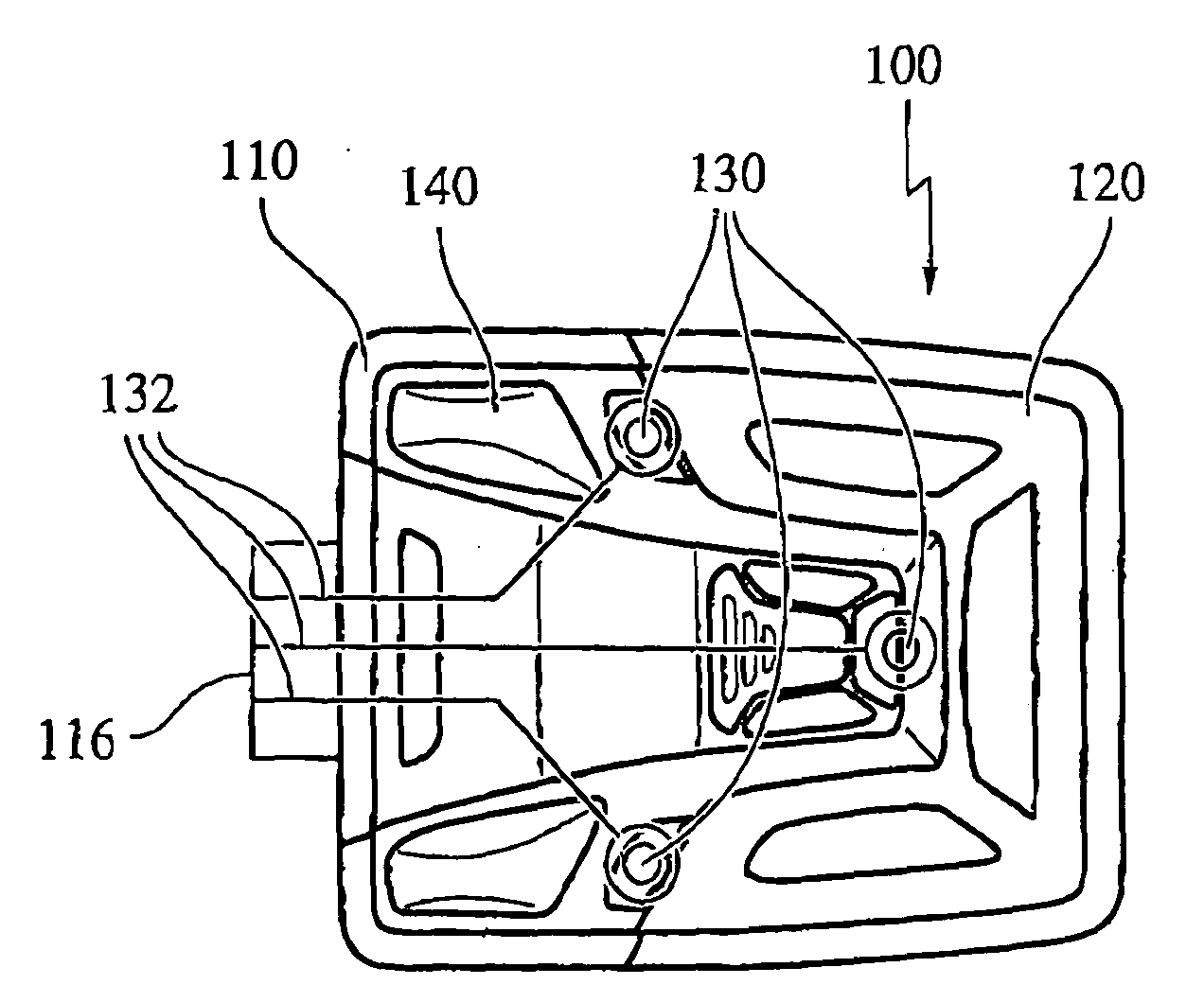
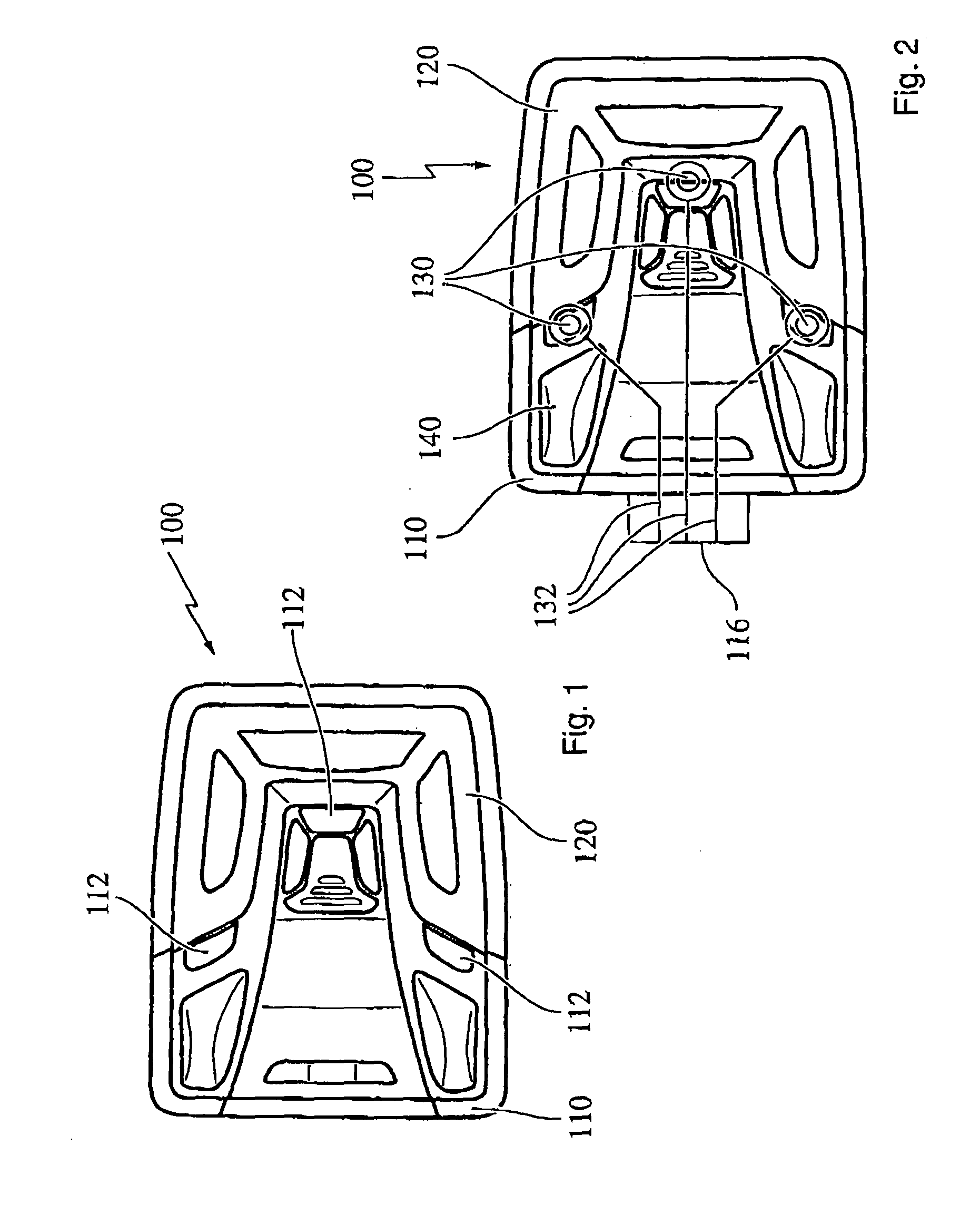
[0037]During operation of an exemplary capacitive switch that may be useable with various exemplary embodiments of this invention, a signal is sent across a conductive pad and the capacitance of the pad is determined. For example, a square wave signal may be provided to the pad. During normal conditions, i.e., when the switch is not being touched, the pad has a low capacitance. As such, a circuit may be provided that quickly charges and drains, such as across a resistor, the pad in tune with the square wave signal. When a foreign object, such as a user's finger, touches or comes within close proximity to the switch, the foreign object increases the capacitance of the pad. The increased capacitance slows the rate at which the pad charges and drains and may be detected by appropriate devices and / or electrical circuits.

[0038]It should be appreciated that the above-outlined exemplary capacitive switch is just one type of numerous devices that may be referred to as capacitive switches an...


PUM

PropertyMeasurementUnit
thicknessaaaaaaaaaa
thicknessaaaaaaaaaa
conductiveaaaaaaaaaa

Abstract

This invention is related to process for the production of a interior trim piece, comprising the steps of: —providing a film layer—applying conductive ink/paint to the back surface of the film layer to provide a circuit path and—attaching a substrate on the back surface of the film layer. This invention further relates to a interior trim piece comprising a film layer with a circuit path on its back surface, whereas the circuit path is made from conductive ink/paint.

Description

BACKGROUND[0001]1. Field of the Invention[0002]This invention is related to process for the production of a interior trim piece, comprising the steps of:[0003]providing a film layer[0004]applying conductive ink / paint to the back surface of the film layer to provide a circuit path and[0005]attaching a substrate on the back surface of the film layer.[0006]This invention further relates to a interior trim piece comprising a film layer with a circuit path on its back surface, whereas the circuit path is made from conductive ink / paint.[0007]2. Background of the Invention[0008]Interior trim pieces provide aesthetic finishes to the interior of vehicles. It is known to provide interior trim pieces that are made by injection molding a substrate to the back surface of a film layer. It is also known to provide interior trim pieces that include electrical circuits, buttons or switches to control various electrical and / or mechanical systems of the vehicle. For example, an overhead console of a v...

Claims


Application Information

Patent Timeline
Patent Type & Authority Applications(United States)
IPC IPC(8): H05K1/00H05K1/09B41F33/00
CPCB29C45/1418B29C45/14639B29C45/14778B29L2031/3041H03K2217/960755C09D5/24C09D11/52H03K17/962B60R2013/0287B29C45/16B60R13/02H03K17/96
Inventor SIMS, MICHAEL J.CATLIN, MICHAEL R.
Owner JOHNSON CONTROLS TECH CO
Why Eureka
Try Eureka