Wireless remote racking mechanism

a technology of electrical switchgear and remote racking, which is applied in the direction of air-break switch, high-tension/heavy-dress switch, electrical apparatus, etc., can solve the problems of cumbersome protective gear, personal danger to the operator's safety, and the need for racking such high-capacity circuit breakers

Active Publication Date: 2011-06-23
SCHNEIDER ELECTRIC USA INC
View PDF15 Cites 35 Cited by
  • Summary
  • Abstract
  • Description
  • Claims
  • Application Information

AI Technical Summary

Benefits of technology

[0003]A motorized racking mechanism for racking a circuit breaker into and out of a cradle of switchgear/board equipment among remove, test, and connected positions is disclosed. The racking mechanism is dedicated to and contained within a standard footprint switchgear/board cabinet, thereby requiring no operator presence at or near the cabinet to move the position of the breaker (and no re-engineering of cabinet size). A wireless transceiver circuit for wirelessly controlling the position of the circuit breaker is also disclosed. A front panel of the cradle includes indicator lights for indicating the position of the circuit break

Problems solved by technology

Racking such high-capacity circuit breakers is a procedure wrought with personal danger to the operator's safety.
A possibility always exists that an explosion will occur due to a fault creating an arc flash, causing significant injury, including burns, or even death to the operator.
Existing techniques have attempted to keep the operator a distance away from the ci

Method used


Image

  • Wireless remote racking mechanism
  • Wireless remote racking mechanism
  • Wireless remote racking mechanism

Examples


Embodiment Construction

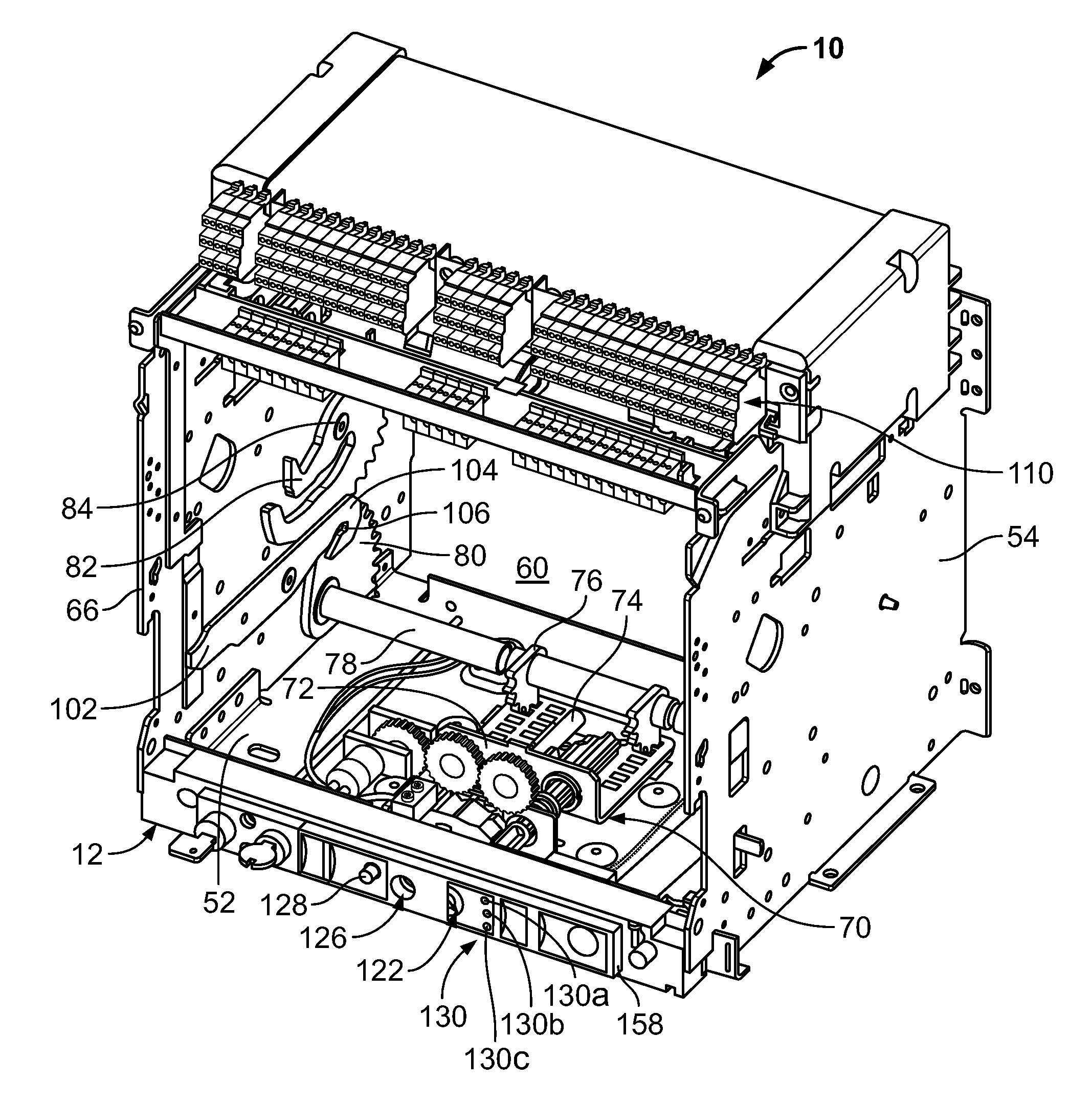
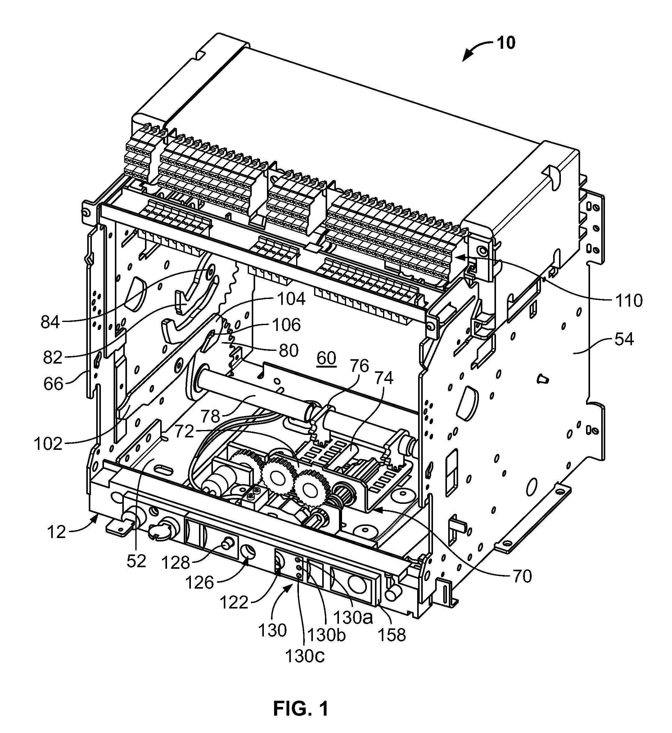
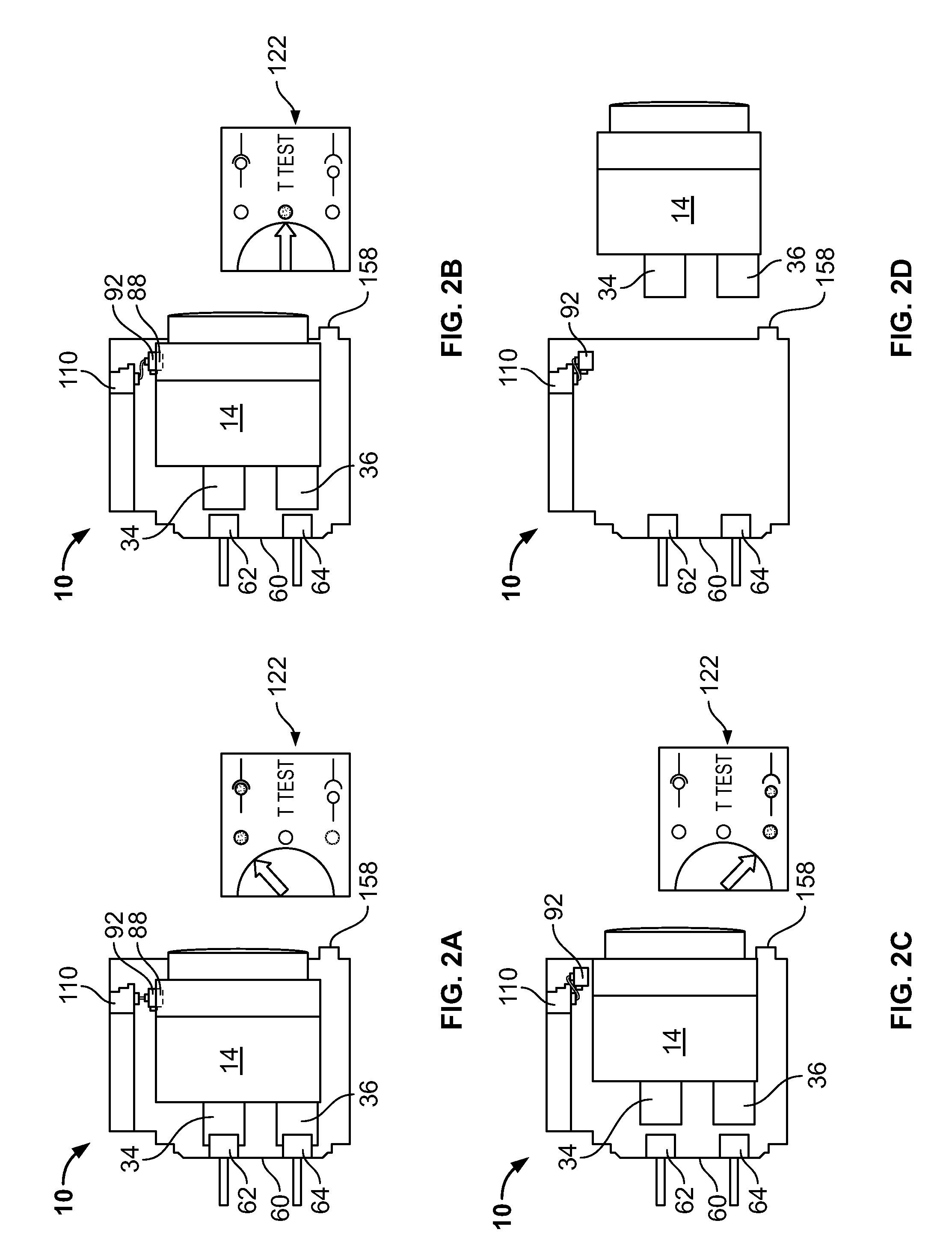
[0029]FIG. 1 is a perspective view of a cradle 10 for use in electrical switchgear equipment (or switchgear / board). The switchgear / board can have a high, medium, or low voltage rating as defined by the American National Standards Institute (ANSI) or can refer to a “switchboard” as defined in Underwriters Laboratory Standard UL891. The terms switchgear and switchboard are referred to interchangeably herein and refer to the same device. The cradle 10 accepts a circuit breaker 14 (shown in FIGS. 2A-2D) inside a frame 12 in the form of an open housing. The open housing includes a base plate 52 and two opposite side walls 54, 56 confining a front opening for insertion or removal of the plug-in circuit breaker 14. The side walls 54, 56 are provided with a pair of parallel draw-in slides 114 (shown in FIG. 4) operable to support and guide the circuit breaker 14 as it is being racked into and out of the cradle 10. The draw-in slides 114 can be seen in FIG. 4 but have been removed in FIG. 1,...


PUM


Abstract

A motorized racking mechanism for racking a circuit breaker into and out of switchgear/board equipment allows for breaker service without operator proximity to the switchgear. A motor fixed to a cradle that receives a circuit breaker is coupled to a power transmission system that turns a control screw. The control screw laterally moves a crown-wheel device that causes the circuit breaker to be moved among a remove, test, and connected positions in response to a button arm being depressed via a front panel of the cradle. The button arm can be depressed under wireless remote control. A solenoid is coupled to a crank detent actuator that includes the button arm, and a wireless module actuates the solenoid, which moves the button arm, causing the motorized movement of the circuit breaker as if the button arm had been manually depressed. Indicator lights are visible on the front panel to indicate the position of the circuit breaker relative to the cradle.

Description

FIELD OF THE INVENTION[0001]The present disclosure relates to racking mechanisms for electrical switchgear / board equipment, and, more particularly, to a motorized internal racking mechanism with wireless control for electrical switchgear / board equipment.BACKGROUND[0002]Electrical switchgear / board equipment (sometimes just called switchgear or switchboard) house very large and heavy circuit breakers that protect loads that can consume thousands of amps of current. The procedure for making or breaking the electrical connections inside the electrical equipment between primary connectors in the circuit breaker and secondary connectors in the switchgear is referred to as racking. Racking such high-capacity circuit breakers is a procedure wrought with personal danger to the operator's safety. A possibility always exists that an explosion will occur due to a fault creating an arc flash, causing significant injury, including burns, or even death to the operator. Existing techniques have att...

Claims


Application Information

Patent Timeline
IPC IPC(8): H01H9/20
CPCH02B11/10H02B11/127
Inventor LEE, GREGORY B.GOBLE, CHRISTOPHER K.
Owner SCHNEIDER ELECTRIC USA INC
Why Eureka
Try Eureka