Vehicle suspension, steering, damping and anti-roll system with linear wheel travel

a technology of suspension springs and linear wheels, which is applied in the direction of shock absorbers, mechanical equipment, transportation and packaging, etc., can solve the problems of lack of adjustability, excessive driver steering strength, and most modern systems continue to be plagued, so as to improve the interior occupant and cargo space, reduce the bulkiness of suspension components, and facilitate the adjustment of suspension springs. the effect of speed

Active Publication Date: 2011-06-23
BEAUJON WILLIAM JAMES
View PDF11 Cites 5 Cited by
  • Summary
  • Abstract
  • Description
  • Claims
  • Application Information

AI Technical Summary

Benefits of technology

[0013]1. reduces the tendency of the wheel to change its turning angle, caster or camber during a bump (bump steer) by using a rod-in-sleeve design to maintain wheel travel in a linear vertical direction, thus maintaining accurate steering angles during wheel travel.
[0021]9. reduces unsprung weight by mounting the spring / shock absorber / anti-roll assembly to the sprung part of the vehicle.

Problems solved by technology

Although many improvements have been made to date, most modern systems continue to be plagued, to some extent, by problems of bump / brake steer, alignment difficulties, inaccurate turning radius angles, alignment changes during road irregularities, anti-roll limitations, lack of adjustability, excessive driver steering strength requirements (often leading to need for power steering), weight, lack of adjustability of suspension rate, lack of adjustability of anti-roll, high unsprung weight and assembly bulkiness.
The end result of this loss in efficiency of transferred forces to the steering arm is an increase in the steering force needed from the driver's steering input (or increased load on the power steering unit).
Drawbacks of this type suspension include bump steer (Ackerman angle and steering direction changes during bumps), brake steer (steering angle changes during braking or undesirable steering turning forces transferred to the driver or power steering unit during braking), caster changes during road bumps (causing wandering of the tire / wheel and steering angle changes), toe-in changes during road bumps (causing inaccurate Ackerman angles, steering wander, loss of traction and tire wear).
High unsprung weight is another drawback of most conventional suspension systems.
Conventional suspensions often incorporate a spring and shock absorber that rest on an A-arm of the suspension, thus contributing to the unsprung weight of the vehicle.
This is a cumbersome process which makes fine-tuning or frequent changes of spring rate very inconvenient and time-consuming
These anti-roll bars are typically non-adjustable metal bars that pivot on a frame bushing and attach to the A-arms of the suspension.
These anti-roll bars contribute to unsprung (and total) suspension weight.
The designs for automotive vehicles have been limited in number and have not been successful thus far.
The lack of success of automotive rod-in-sleeve designs is likely multifactorial.
Rod-in-sleeve designs may have not adequately overcome enough of the limitations of conventional suspension systems (as discussed above) to justify retooling.
Other reasons for the lack of success with rod-in-sleeve designs may be the new problems encountered with some designs including bulkiness, lack of strength, lack of adequate steerability, inadequate lubrication mechanisms, difficulty integrating anti-roll mechanisms and poor durability.

Method used


Image

  • Vehicle suspension, steering, damping and anti-roll system with linear wheel travel
  • Vehicle suspension, steering, damping and anti-roll system with linear wheel travel
  • Vehicle suspension, steering, damping and anti-roll system with linear wheel travel

Examples


Embodiment Construction

Description of Components Involved in Suspension Travel

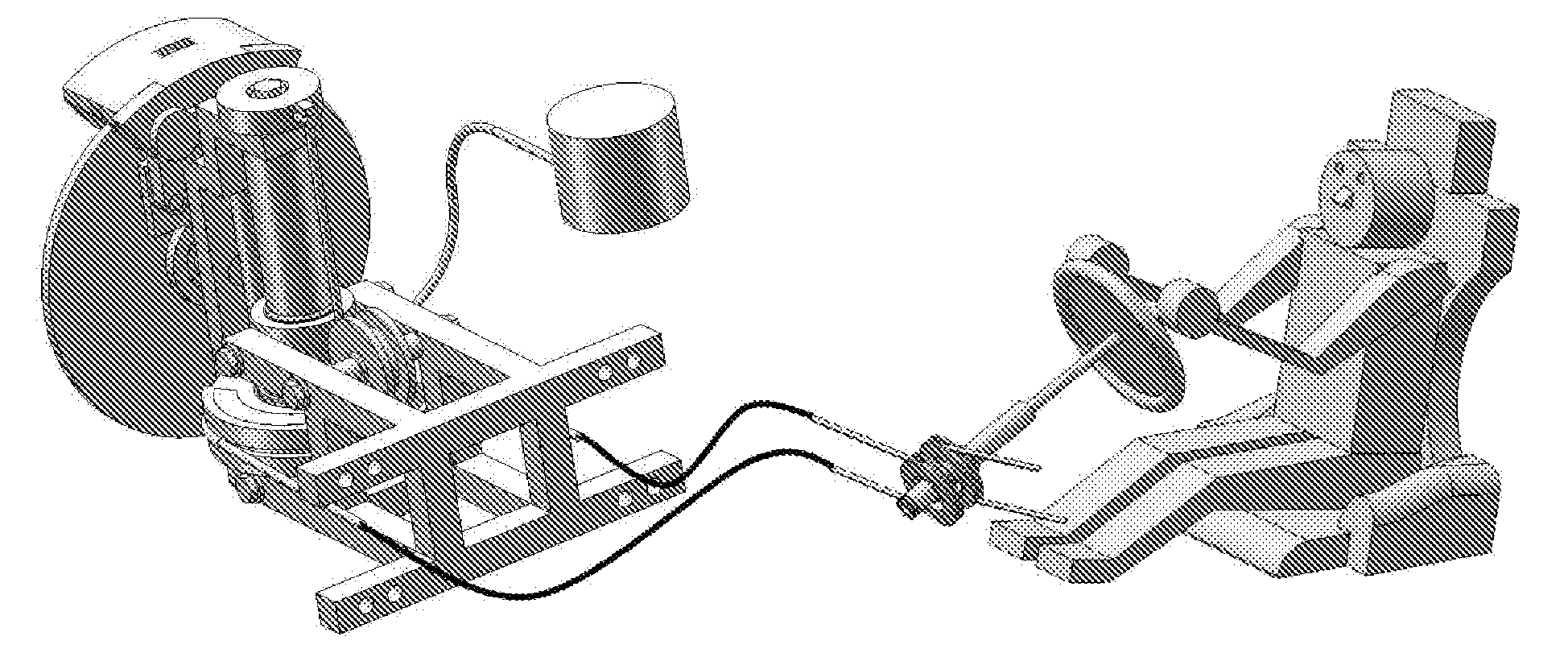
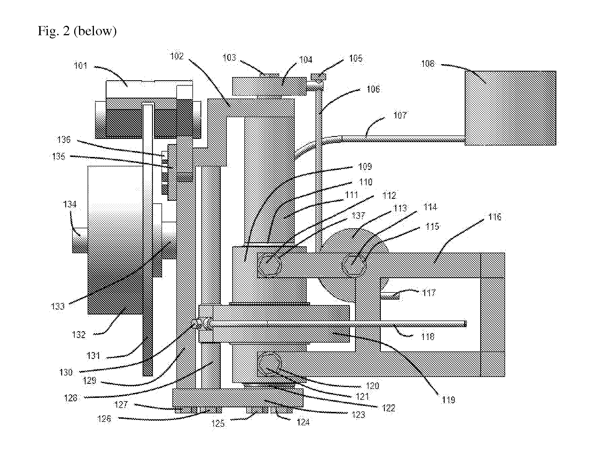
[0062]The wheel attaches to hub 132. During road bumps, the upward tire force is transferred to the main rod of the knuckle 111 via the wheel spindle 133 and spindle frame of the knuckle 129. This upward force causes the knuckle assembly to move in an upward, linear direction. The knuckle assembly components move up and down in concert. The knuckle assembly components consist of the spindle support frame 129, the upper knuckle frame 102, the main rod 111, the lower end cap 123 and the secondary rod 128. The knuckle assembly moves up or down relative to the subframe 116 (and vehicle frame) while sliding in the sleeve 109. As the knuckle assembly moves upward, the upper part of the suspension cable 106 moves upward and increases cable tension. The suspension cable contains a stop 105 at its top end. Upward movements of the knuckle assembly are transmitted to washer 151, inner bearing race of bearing 150, to outer bearing race of b...


PUM


Abstract

A vehicle suspension, steering, damping and anti-roll system for a wheeled vehicle. Unlike most previous vehicle suspension and steering systems, this invention uses a rod-in-sleeve design for the front and rear suspension assemblies to allow vertical linear wheel knuckle movement of the wheels. This invention is unusual by using a cable-operated steering system and also by using cables to transfer cable tension from upward wheel movement to remote spring / shock absorber assemblies. Also unique is the use of a spring / shock absorber assembly arrangement that provides both suspension and anti-roll effects for a pair of right and left wheels in the same unit. The rear suspension proposed shares some similarities to the front suspension and consists of a dual rod-in-sleeve design with cables that transfer forces from road bumps to a remote spring assembly.

Description

CROSS-REFERENCE TO RELATED APPLICATIONS[0001]Not applicableSTATEMENT REGARDING FEDERALLY SPONSORED RESEARCH OR DEVELOPMENT[0002]Not applicableREFERENCE TO SEQUENCE LISTING, A TABLE, OR A COMPUTER PROGRAM LISTING COMPACT DISC APPENDIX[0003]Not applicableBACKGROUND OF THE INVENTION[0004]Vehicle suspension and steering system variations for 4 or 3-wheel vehicle designs have been extensively researched and refined. Although many improvements have been made to date, most modern systems continue to be plagued, to some extent, by problems of bump / brake steer, alignment difficulties, inaccurate turning radius angles, alignment changes during road irregularities, anti-roll limitations, lack of adjustability, excessive driver steering strength requirements (often leading to need for power steering), weight, lack of adjustability of suspension rate, lack of adjustability of anti-roll, high unsprung weight and assembly bulkiness. Some of these drawbacks of conventional systems are described bel...

Claims


Application Information

Patent Timeline
Patent Type & Authority Applications(United States)
IPC IPC(8): B60G3/01B60G15/06B62D3/02B60R17/00
CPCB60G3/01B62D3/02B60G2204/30B60G15/06
Inventor BEAUJON, WILLIAM JAMES
Owner BEAUJON WILLIAM JAMES
Why Eureka
Try Eureka