Fuse element having damping structure

a technology of damping structure and fuse element, which is applied in the field of fuse element, can solve problems such as failure of the entire modul

Inactive Publication Date: 2011-06-23
ATIEVA USA INC
View PDF35 Cites 17 Cited by
  • Summary
  • Abstract
  • Description
  • Claims
  • Application Information

AI Technical Summary

Benefits of technology

[0016]FIG. 1 is a schematic diagram illustrating conventional battery cells arranged and positioned in a box;
[0017]FIG. 2 is a schematic diagram illustrating the structure of a conventional fuse element;
[0018]FIG. 3 is a circuit diagram showing that the fuse element of FIG. 2 is in an electrically connected state;
[0019]FIG. 4 is another circuit diagram showing that the fuse element of FIG. 3 is loosened from the fastened position, causing generation of extra resistance;
[0020]FIG. 5 is a schematic diagram showing that a fuse element having a damping structure according to the first preferred embodiment of the invention is connected to a battery cell;
[0021]FIG. 6 is an enlarged diagram showing the fuse element of FIG. 5;

Problems solved by technology

By virtue of the protection provided by the fuse element, the malfunction of any of the battery cells due to internal or external means will not easily result in failure of the entire module.

Method used


Image

  • Fuse element having damping structure
  • Fuse element having damping structure
  • Fuse element having damping structure

Examples


Embodiment Construction

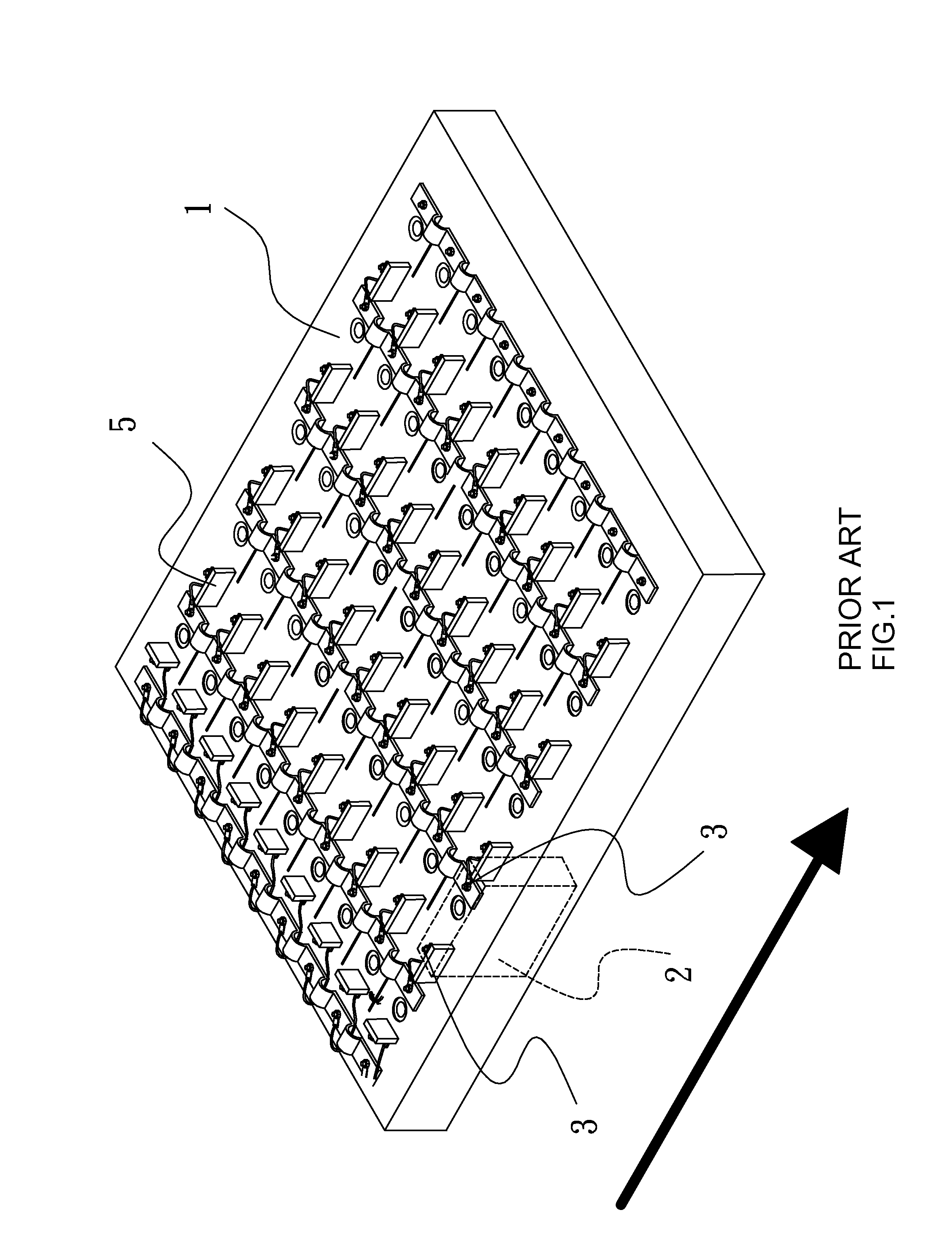
[0024]A fuse element having a damping structure according to the invention is illustrated herein to be mounted in a power source module. In this embodiment, an energy storage unit is illustrated as a battery pack composed of a single battery cell, and a single fuse element is connected correspondingly to a single battery cell. However, it is readily apparent to those skilled in the art that the arrangement described above is not limitative, and that a capacitor or an inductor may store energy in an electric field or in a magnetic field and serve as an energy storage unit for providing electric energy when needed. The fuse element according to the invention is also not limited to be used only in a power source module.

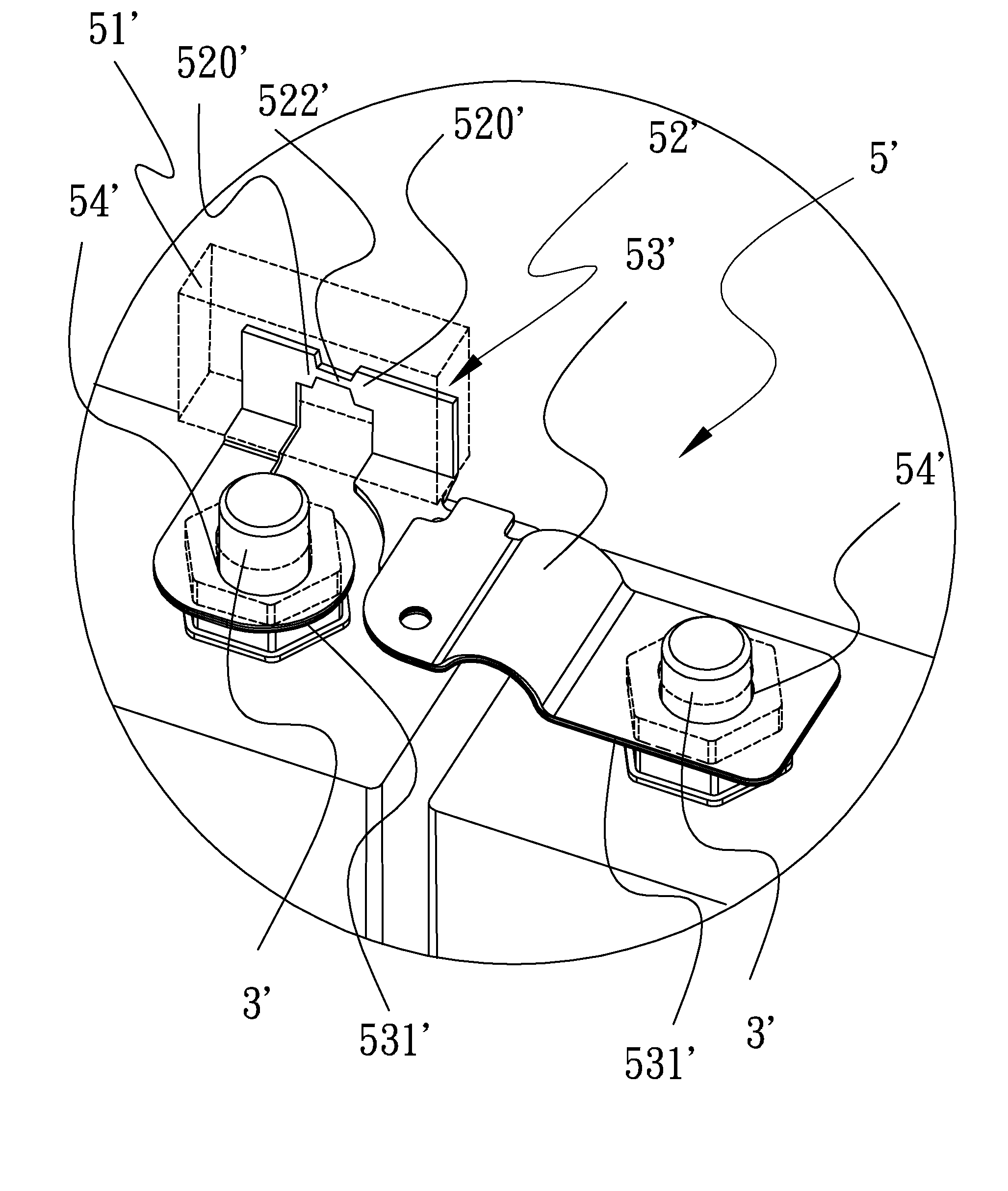
[0025]Referring to the first preferred embodiment shown in FIGS. 5 and 6, a fuse body 52′ includes two ends 522′ and a meltable portion 520′ which is coupled between the two ends 522′ and has a width narrower than that of the ends 522′. The fuse body 52′ is encapsulated ...


PUM


Abstract

A fuse element having a damping structure is disclosed. The fuse element includes a fuse body having two ends, a housing for encapsulating the fuse body and two extending anchor sections connected to the two ends. A meltable portion is coupled between the two ends and housed by the housing, so that the metable portion, when melted, will not contaminate the surrounding space. At least one of the anchor sections has at least one flexible conductive portion. If the fuse element is mounted in a circuit and subjected to shock and vibration, the flexible conductive portion will absorb the mechanical stresses placed on the terminals and the fuse body. As a result, the safety and reliability of the fuse element and the apparatus to which it is connected is significantly enhanced.

Description

FIELD OF THE INVENTION[0001]The present invention relates to a fuse element, and more particularly, to a fuse element having a damping structure.DESCRIPTION OF THE RELATED ART[0002]Concerns on rising oil prices and increasing carbon emissions have propelled auto makers to switch from gasoline to electric power in the auto market. However, the battery pack used in electric vehicles must pass strict environment tests and meet the crash safety standards under different road conditions, and must last for a long time. Therefore, connecting batteries in a safer way, maximizing the energy stored in batteries, prolonging the endurance of batteries and preventing batteries from forming thermal chain reactions in case of accident are key issues for developing the equipments of this type.[0003]As shown in FIG. 1, a conventional battery module for use in an electric-powered vehicle usually includes a plurality of rectangular-shaped battery cells arranged as a matrix form and mounted in a box 1,...

Claims


Application Information

Patent Timeline
Patent Type & Authority Applications(United States)
IPC IPC(8): H02J1/00H01H85/02
CPCH01H3/60H01H85/0017H01M2200/103H01H2085/025H01M2/206H01H85/0241Y02E60/10
Inventor CHUANG, CHIA-MING
Owner ATIEVA USA INC
Why Eureka
Try Eureka