Electric machine having spray and sump cooling

a technology of electric machines and sump pumps, which is applied in the direction of cooling/ventilation arrangements, dynamo-electric machines, electrical appliances, etc., can solve the problems of not being able to stick the stator and the rotor to each other, and achieve the effect of preventing the filling of electric machines and simplifying the design

Inactive Publication Date: 2011-06-23
ROBERT BOSCH GMBH
View PDF7 Cites 46 Cited by
  • Summary
  • Abstract
  • Description
  • Claims
  • Application Information

AI Technical Summary

Benefits of technology

[0005]According to the present invention, it is provided that the cooling device further has at least one coolant spray device for spraying the electrical assemblies with coolant, the sump pan having a coolant discharge which, during non-operation of the electric machine, feeds the coolant into a coolant reservoir and is dimensioned so that, during operation of the electric machine at a specified coolant volume flow of the coolant spray device, a coolant level, which wets the rotor, sets in in the sump pan. Because of the coolant discharge, the present invention makes possible a variable coolant level in the sump pan. During operation of the electric machine, to achieve coolant distribution, the specified coolant flow is sprayed via the coolant spray device into the electric machine. In the process, the coolant discharge prevents the filling up of the electric machine with coolant by feeding coolant from the sump pan into the coolant r...

Problems solved by technology

Consequently, the sticking of the stator and the rotor to each other is n...

Method used


Image

  • Electric machine having spray and sump cooling
  • Electric machine having spray and sump cooling
  • Electric machine having spray and sump cooling

Examples


Embodiment Construction

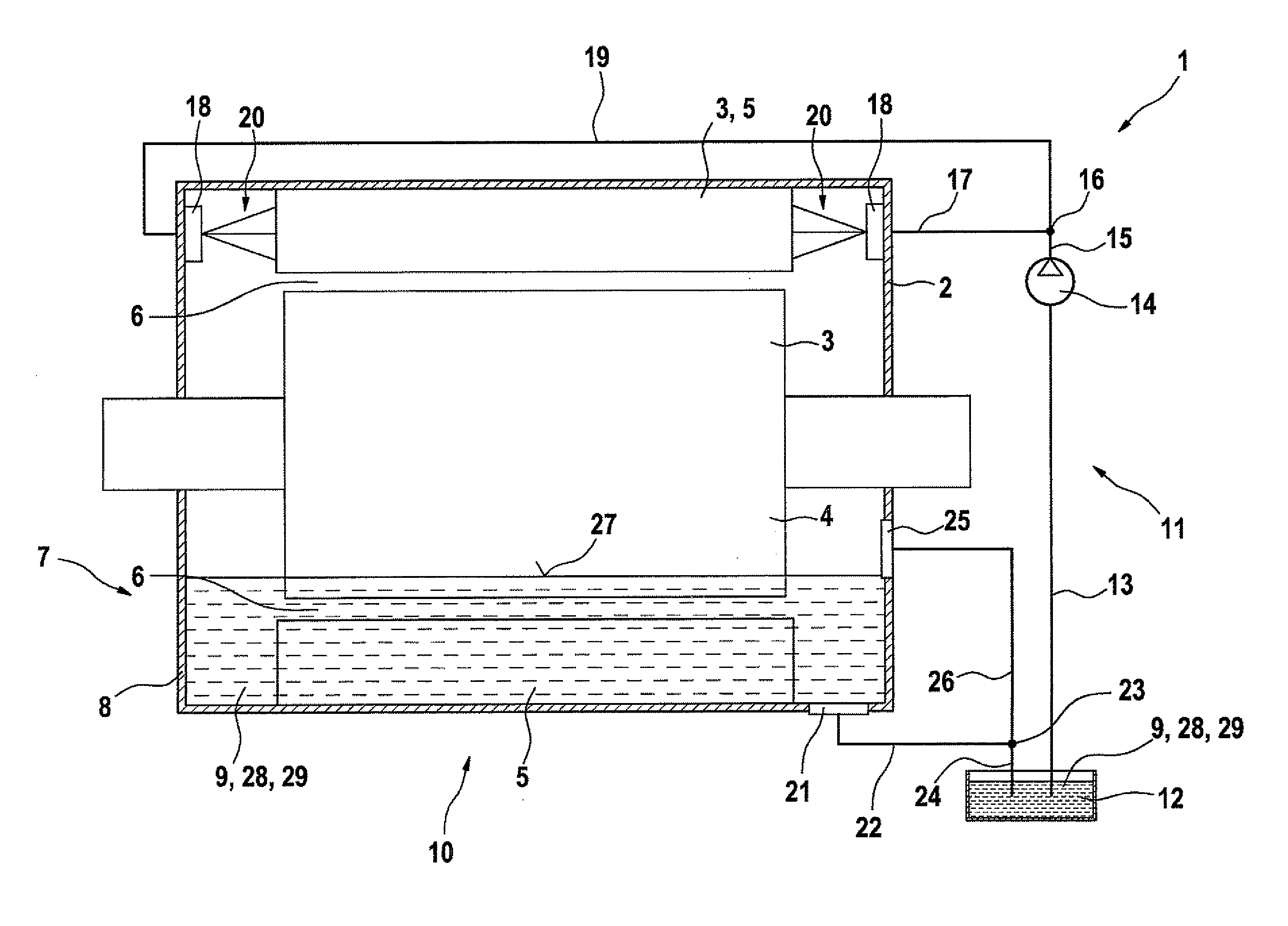
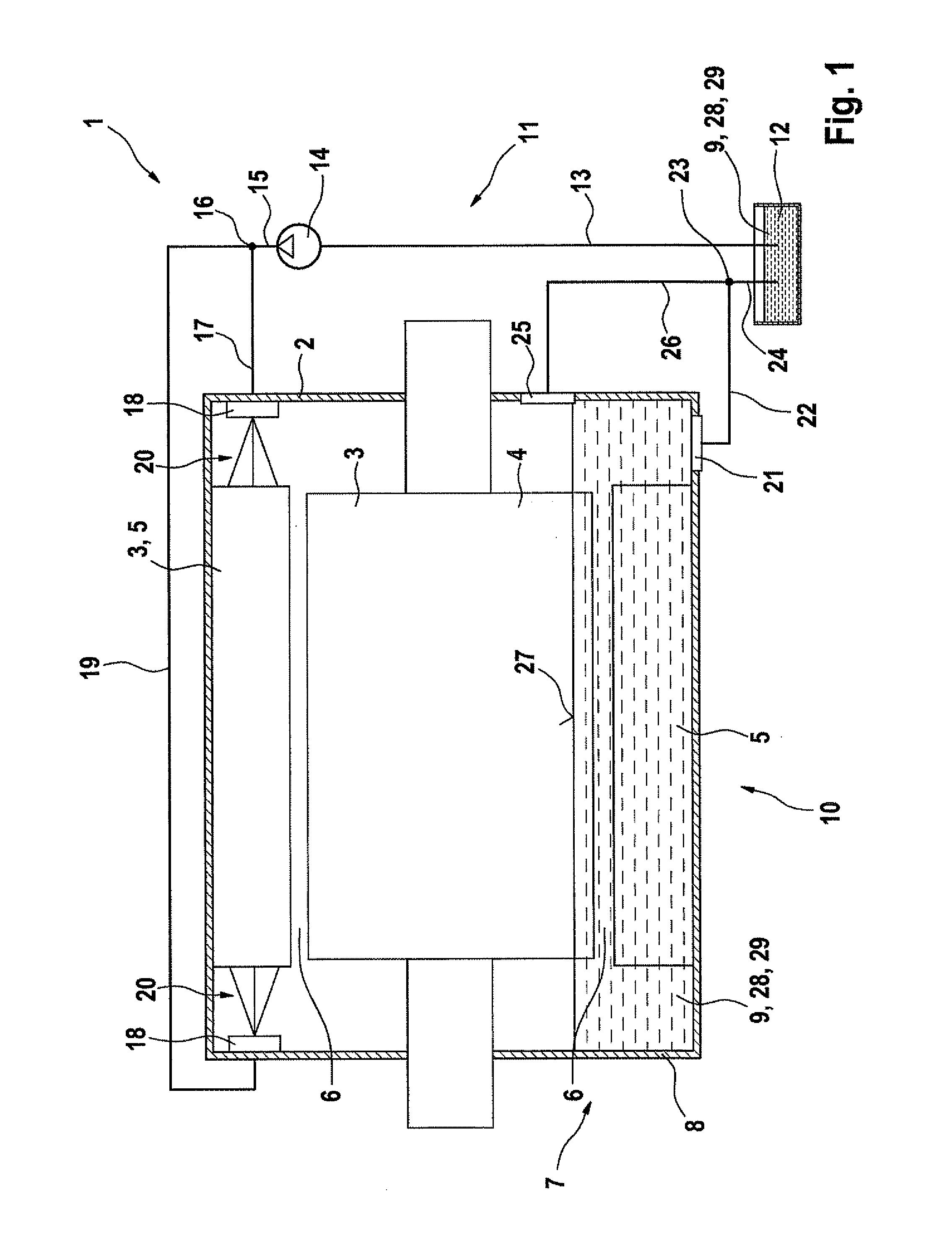
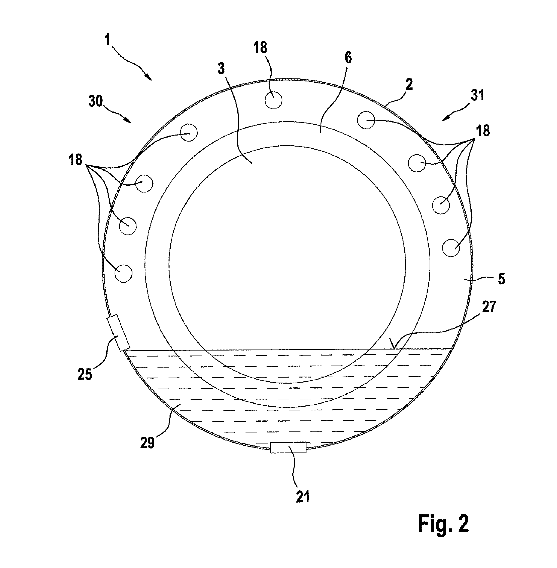
[0014]FIG. 1 shows an electric machine 1 having a housing 2, which has a first electrical assembly 3, which is designed as a rotor 4. In addition, housing 2 shows a second electrical assembly 3, which is designed as stator 5, an air gap 6 forming between rotor 4 and stator 5, which has a circular cross section. In its lower region 7, housing 2 is developed as a sump pan 8, in which there is a coolant 9. Sump pan 8 and coolant 9 belong to a cooling device 10, which has a coolant circulation 11. Coolant circulation 11 runs from a coolant reservoir 12 to a coolant pump 14 via a line 13. Starting from coolant pump 14, coolant 9 is passed on via a line 15 to a node 16 and from node 16 via a line 17 to a first coolant spray device 18. Furthermore, starting from node 16, coolant 9 is conveyed via a line 19 to a second coolant spray device 18. Coolant spray devices 18 each generate a coolant spray jet 20, which sprays stator 5 with coolant 9. After that, coolant 9 drips into sump pan 8. Sum...


PUM


Abstract

An electric machine has a housing, and in the housing has at least one electrical assembly including a rotor, and having a cooling device which, in the lower region of the housing, has a sump pan that is situated or developed there for a coolant. The cooling device further has at least one coolant spray device for spraying the electrical assembly with coolant, the sump pan having a coolant discharge which, during non-operation of the electric machine, feeds the coolant into a coolant reservoir and is dimensioned so that, during operation of the electric machine at a specified coolant volume flow of the coolant spray device, a coolant level, which wets the rotor, sets in in the sump pan. A corresponding method is also provided.

Description

FIELD OF THE INVENTION[0001]The present invention relates to an electric machine which has a housing and in the housing at least one electrical assembly including a rotor, and having a cooling device which, in the lower region of the housing, has a sump pan situated or developed there for a coolant. The present invention also relates to a corresponding method.BACKGROUND INFORMATION[0002]For cooling an electric machine, it is known that one may apply oil to electrical assemblies. In the case of nozzle oil cooling, this is achieved by having a plurality of nozzles spraying the electrical assemblies to be cooled using oil. This requires a costly design.[0003]A further possibility is presented by sump cooling, which has a sump into which the electrical assemblies, that are to be cooled, are dipped. Sump cooling requires fluid-level monitoring, which is difficult to implement. Furthermore, at low temperatures the oil becomes viscous and makes the electrical assemblies of the electric mac...

Claims


Application Information

Patent Timeline
IPC IPC(8): H02K9/19
CPCH02K9/19
Inventor ESSE, PAUL
Owner ROBERT BOSCH GMBH
Why Eureka
Try Eureka