Commutator for an electrical machine, and electrical machine

a technology of commutator and electrical machine, which is applied in the direction of current collector, rotary current collector, electrical apparatus, etc., can solve the problems of difficult geometric replacement of rotor or machine from the same series for different operating voltages, unwanted properties of electrical machines, and winding heating, etc., and achieve the effect of compact structur

Active Publication Date: 2011-06-23
ROBERT BOSCH GMBH
View PDF10 Cites 0 Cited by
  • Summary
  • Abstract
  • Description
  • Claims
  • Application Information

AI Technical Summary

Benefits of technology

[0016]In an alternative embodiment, it is also possible that the ends are embodied in hook-shaped fashion and are bent over radially outward. In this feature, it is possible in particular to dispense with the embodiment of slots or the like in the ends of the laminations, so that the manufacture of the laminations and of the commutator can be done relatively inexpensively.
[0017]Additional guidance of the wire ends and a secure electrical disconnection of adjacent wire ends is furthermore possible if the commutator body comprises plastic and is embodied as a shaped casting part, if the commutator body, on the side oriented toward the ends of the laminations, has guide zones for the wire ends, and if the guide zones are embodied as indented regio...

Problems solved by technology

However, all of these provisions can lead to unwanted properties of the electrical machine.
For instance, the geometric replaceability of rotors or machine...

Method used


Image

  • Commutator for an electrical machine, and electrical machine
  • Commutator for an electrical machine, and electrical machine
  • Commutator for an electrical machine, and electrical machine

Examples


Embodiment Construction

[0032]Identical components and components with the same function are provided with the same reference numerals in the drawings.

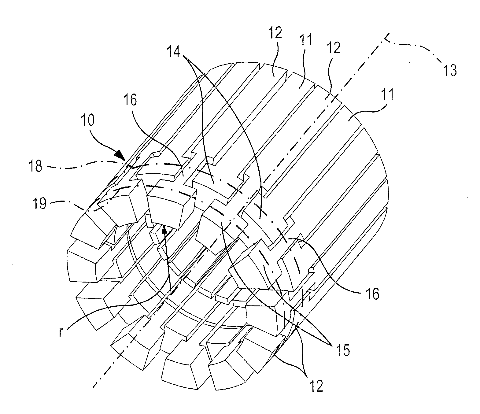
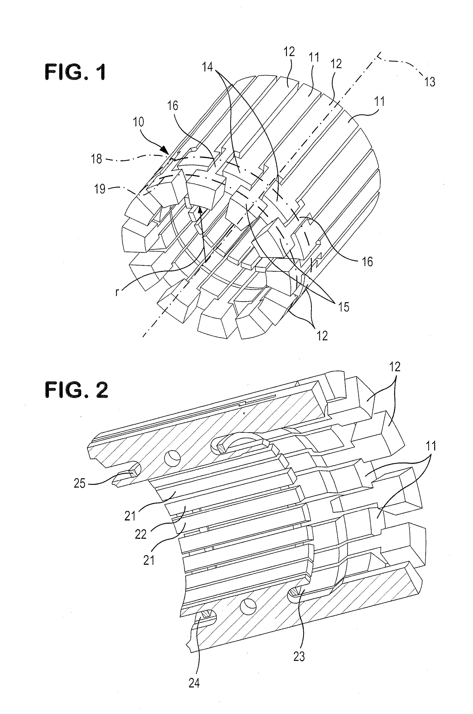
[0033]In FIG. 1, parts of a commutator 10 of the invention are shown, of the kind used in particular as components of an electrical machine, and especially preferably as components of a direct current motor.

[0034]In FIG. 1, a plurality of laminations 11 and 12 can be seen, spaced apart from one another at an identical radial spacing r from a longitudinal axis 13 of the commutator 10 and that form a common circumferential surface. The ends 14 and 15 of the laminations 11 and 12, which ends are disposed on the winding side of an armature, not shown in FIG. 1, are each embodied as T-shaped. In the case of the laminations 11, each of the laminations 11 has a constant width except for the ends 14, but the other laminations 12 have a portion 16 of reduced width. The T-shaped ends 14 of the first group of laminations 11 are disposed in the portions 16 of reduced wi...


PUM


Abstract

The invention relates to a commutator for an electrical machine, having a commutator body on the outer circumference of which a plurality of electrically conductive, elongated laminations are disposed parallel to the longitudinal axis of the commutator. The laminations disposed adjacent to one another are electrically insulated from one another. The ends of the laminations, oriented toward the wire windings of an armature, are each electrically conductively connected to at least one wire end. According to the invention, it is provided that the ends of the laminations end, perpendicular to the longitudinal axis of the commutator, in planes offset from one another.

Description

CROSS-REFERENCE TO RELATED APPLICATION[0001]This application is based on German Patent Application 10 2009 054 651.0 filed on Dec. 15, 2009.BACKGROUND OF THE INVENTION[0002]1. Field of the Invention[0003]The invention relates to a commutator for an electrical machine.[0004]2. Description of the Prior Art[0005]One such commutator is already general prior art in a direct current motor, and has laminations disposed on a commutator body that are electrically contacted or connected, on the side toward one winding side of an armature, to the winding ends of the wire windings. As a result of the centrifugal forces engendered by the rotation of the armature, the connections between the wire ends or winding ends and the laminations must be embodied so as to be stable, even at relatively high rotary speeds of the armature.[0006]It is therefore known for the ends, toward the wire windings, of the laminations to be bent over radially outward and back, so that the ends of the laminations point a...

Claims


Application Information

Patent Timeline
IPC IPC(8): H01R39/32
CPCH01R39/32H01R39/04
Inventor RIEKER, WERNERSCHOEN, LUDWIG
Owner ROBERT BOSCH GMBH
Why Eureka
Try Eureka