Protective device with automated self-test

a protection device and self-test technology, applied in the direction of circuit-breaking switches, testing circuits, instruments, etc., can solve the problems of protective devices permanently denying power to load terminals

Inactive Publication Date: 2011-06-23
PASS SEYMOUR
View PDF36 Cites 23 Cited by
  • Summary
  • Abstract
  • Description
  • Claims
  • Application Information

AI Technical Summary

Benefits of technology

[0013]The present invention provides a variety of methods for indicating that an end-of-life, or device failure, has occurred. In one embodiment, the indicator is actuated automatically by a self-test mechanism that automatically identifies an end-of-life condition. In another method provided by the present invention, the end-of-life condition is detected by manually depressing a test button. The test button initiates a test procedure. If the protective device fails to generate a test acceptance signal in response to the test procedure, the indicator is energized.

Problems solved by technology

The protective device permanently denies power to the load terminals after the predetermined amount of time has elapsed.
While the user may be able to reset the protective device to restore power to the load terminals, the protective device permanently denies power to the load terminals after a predetermined period of time has elapsed.
The unsuccessful test result occurs when the protective circuit assembly does not respond to the self-test signal within a predetermined period of time.

Method used


Image

  • Protective device with automated self-test
  • Protective device with automated self-test
  • Protective device with automated self-test

Examples


second embodiment

[0084]As embodied herein and depicted in FIG. 12, a schematic of a circuit protection device in accordance with the present invention is disclosed. FIG. 12 is a schematic diagram of an alternate embodiment in which the fault simulation circuit generates a simulated negative half cycle grounded neutral signal. Reference is made to U.S. patent application Ser. No. 10 / 768,530, which is incorporated herein by reference as though fully set forth in its entirety, for a more detailed explanation of the fault simulation signal. Note that test circuit 1128 does not include diode 4.

[0085]The GFI circuit 102 in FIG. 12 includes a transformer 2 that is configured to sense a load-side ground fault when there is a difference in current between the hot and neutral conductors. Transformer 2 transmits a sensed signal to detector circuit 16. GFI circuit 102 also includes a grounded neutral transmitter 3 that is configured to detect grounded neutral conditions. Those skilled in the art understand that...

third embodiment

[0092]As embodied herein and depicted in FIG. 13, a schematic of a circuit protection device in accordance with the present invention is disclosed. FIG. 13 is a schematic diagram that illustrates how the present invention may be applied to a general protective device 300. Further, FIG. 13 incorporates a redundant solenoid.

[0093]If sensor 1302 is included, the protective device is an AFCI. If transformers 2 and 3 are included, the protective device is a GFCI. If sensor 1302, and transformers 2 and 3 are included, the protective device is a combination AFCI-GFCI. Stated generally, the protective device may include one or more, or a combination of sensors configured to sense one or more type of hazardous conditions in the load, or in the AC electrical circuit supplying power to the load. Sensor 1302 senses an arc fault signature in load current. Detector 1304 is similar to ground fault detector 16, but is configured to detect signals from any of the variety of sensors employed in the d...

fourth embodiment

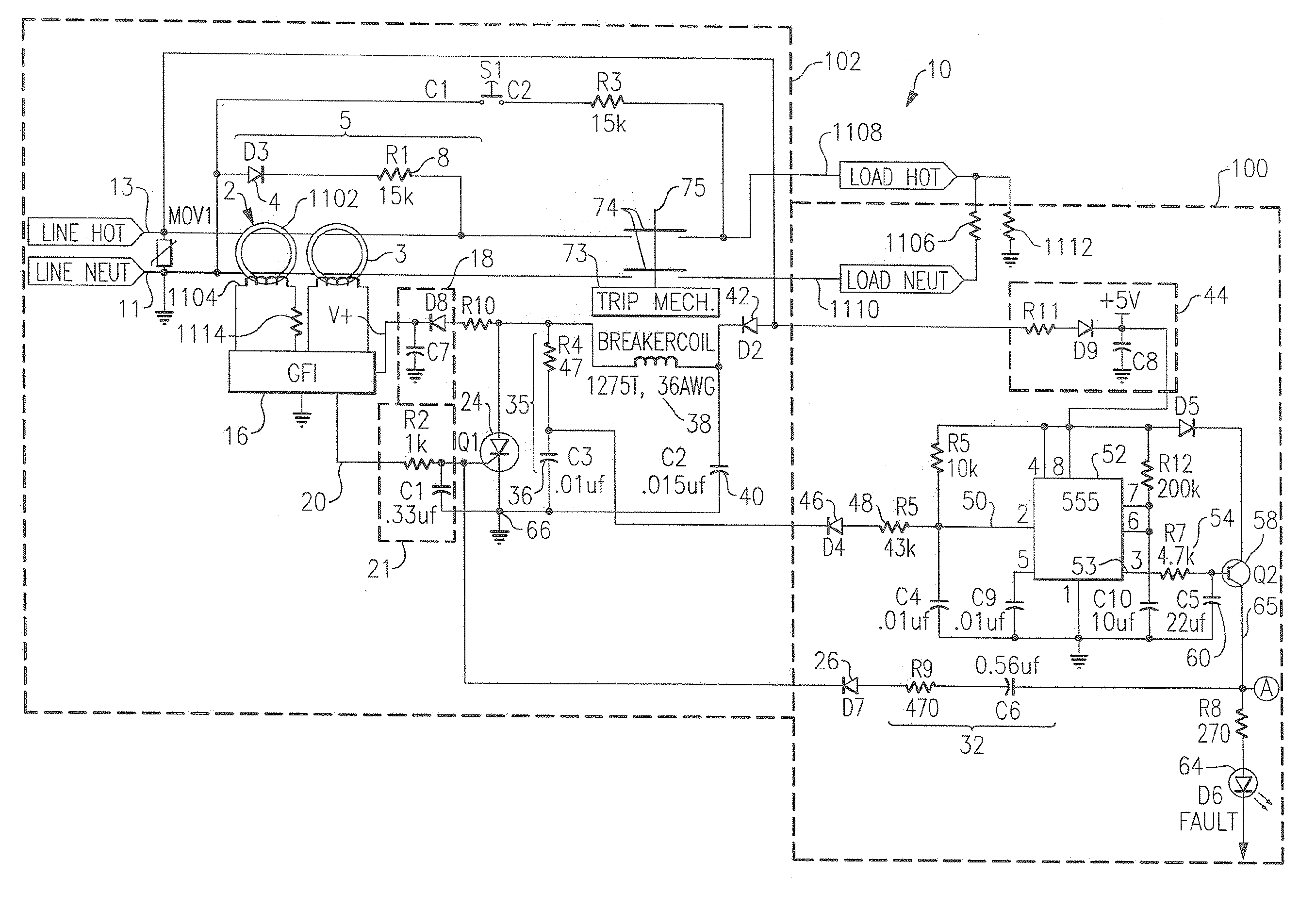
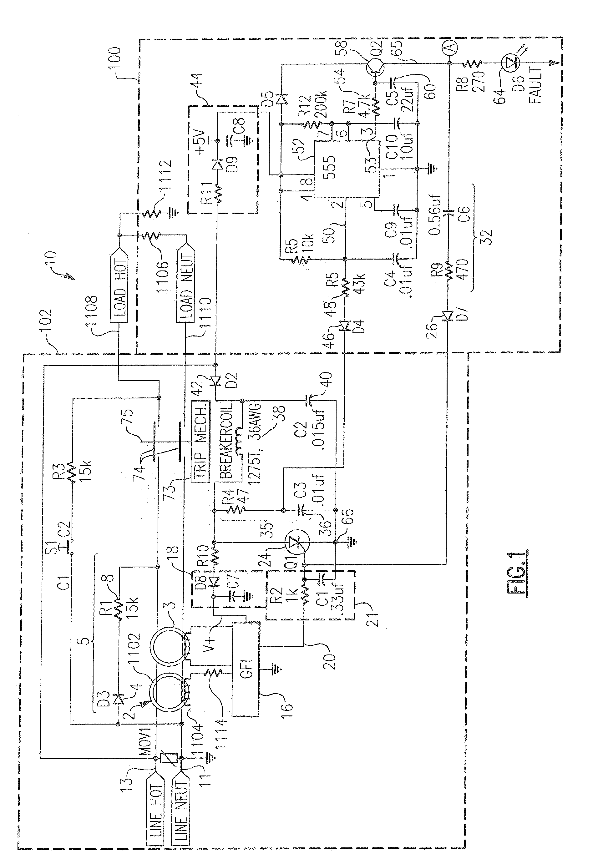
[0120]As embodied herein and depicted in FIG. 20, a schematic of a circuit protection device in accordance with the present invention is disclosed. GFCI 10 includes a GFI circuit 102 and a self test checking circuit 2110. GFI circuit 102 includes a standard GFCI device in which a load-side ground fault is sensed by a differential transformer 2. A transformer 3, which is a grounded neutral transmitter, is used to sense grounded neutral faults. The transformer 2 output is processed by a GFI detector circuit 16 which produces a signal on output 20 that, after filtering in a circuit 21, activates a trip SCR 24. When SCR 24 turns ON, it activates a solenoid 38 which in turn operates a mouse trap device 73, releasing a plurality of contacts 74 and interrupting the load.

[0121]An across-the-line metal oxide varistor (MOV1), also commonly referred to as a movistor, may be included in the protective device such as MOV 15 to prevent damage of the protective device from high voltage surges from...


PUM


Abstract

The present invention is directed to an electrical wiring device that includes at least one sensor that provides a sensor output signal corresponding to electrical perturbations propagating on the plurality of line terminals or the plurality of load terminals. A protective circuit assembly configured to detect a fault condition when the sensor output signal substantially corresponds to at least one predetermined fault criterion and generate a trip actuation signal in response thereto. A solenoid coil is configured to generate a trip actuation force in response to the trip actuation signal. A circuit interrupter assembly includes movable contacts configured to be driven into a tripped state in response to the trip actuation force. An automatic fault simulation circuit is configured to generate a self-test signal without execution of software code. The self-test signal is generated such that it is sensed by the at least one sensor if the at least one sensor is operational. An end-of-life detection circuit is coupled to the protective circuit assembly. The end-of-life detection circuit is configured to monitor the protective circuit assembly without execution of software code. The end-of-life detection circuit is configured to substantially inhibit the trip actuation force when the protective circuit assembly detects the fault condition and generates the trip actuation signal in response to the self-test signal. The end-of-life detection circuit is configured to generate an end-of-life response if the protective circuit assembly does not respond to the self-test signal within a predetermined period of time.

Description

CROSS-REFERENCE TO RELATED APPLICATIONS[0001]This is a continuation of U.S. patent application Ser. No. 12 / 247,848 filed on Oct. 8, 2008, which is a continuation of U.S. patent application Ser. No. 11 / 025,509 filed on Dec. 29, 2004, now abandoned, which is a continuation-in-part of U.S. patent application Ser. No. 10 / 868,610 filed on Jun. 15, 2004, now U.S. Pat. No. 6,980,005, which is a continuation-in-part of U.S. patent application Ser. No. 10 / 668,654 filed on Sep. 23, 2003, now U.S. Pat. No. 6,873,158, the content of which is relied upon and incorporated herein by reference in its entirety, and the benefit of priority under 35 U.S.C. §120 is hereby claimed. U.S. patent application Ser. No. 10 / 668,654 claims priority under 35 U.S.C. §120 based on U.S. Pat. No. 6,674,289, which was filed on Nov. 29, 2000, the content of which is also relied upon and incorporated herein by reference in its entirety. U.S. Pat. No. 6,674,289 claims priority under 35 U.S.C. §119(e) based on U.S. Provi...

Claims


Application Information

Patent Timeline
Patent Type & Authority Applications(United States)
IPC IPC(8): G01R31/327G01R31/14
CPCG01R31/024G01R31/14H02H3/335H01H73/045H01H2071/044G01R31/3277G01R31/52G01R31/28G01R31/2829G01R35/00
Inventor RICHARDS, JEFFREY C.FINLAY, SR., DAVID A.MACBETH, BRUCE F.PACKARD, THOMAS N.
Owner PASS SEYMOUR
Why Eureka
Try Eureka