Fiber optic interferometer and method for determining physical state parameters in the interior of a fiber coil of a fiber optic interferometer

a fiber optic interferometer and interior technology, applied in the direction of speed measurement using gyroscopic effects, instruments, surveying and navigation, etc., can solve the problems of not being able to directly measure the instantaneous state at the interior of the optical fiber, and not being able to produce the same propagation time of light beams,

Inactive Publication Date: 2011-06-23
NORSROP GRUMAN LITEF GMBKH
View PDF7 Cites 5 Cited by
  • Summary
  • Abstract
  • Description
  • Claims
  • Application Information

AI Technical Summary

Benefits of technology

[0011]In a second aspect, the invention provides a method for determining physical state parameters in the interior of a fiber coil of a fiber optic interferometer of the type in which two partial light beams are coupled into an optical fiber that is wound to form the fiber coil. According to the method, information about physical state parameters in the interior of the fiber coil is obtained based on the reflection wavelength of a Bragg structure that is integrated into the fiber coil. Such Bragg structure comprises an optical fiber having a periodically varying refractive index.

Problems solved by technology

The refractive index depends in turn both directly (due to the material property of the fiber) and indirectly on temperature as a change in length of the fiber due to temperature is accompanied by varying, spatially locally distributed mechanical stresses σ in the inner fiber core of the wound fiber that can lead to a change in refractive index n. When local mechanical stresses on the fiber are intensified, cross-couplings between the fast and the slow axes of a polarization-maintaining optical fiber can also occur that result in considerable changes in propagation time.
A calibration preceding operation of the sensor has the disadvantage that the conditions under which the sensor is intended to be used must be previously defined.
In such an arrangement, however, it is not possible to directly measure the instantaneous state at the interior of the optical fiber.
Additionally, an identical temperature does not necessarily produce the same propagation time of the light beam.
Technical procedural difficulties would occur, however, when winding the optical fiber, such as the rebound of the optical fiber as a result of bulges within the coil at the locations of the sensors.

Method used


Image

  • Fiber optic interferometer and method for determining physical state parameters in the interior of a fiber coil of a fiber optic interferometer
  • Fiber optic interferometer and method for determining physical state parameters in the interior of a fiber coil of a fiber optic interferometer
  • Fiber optic interferometer and method for determining physical state parameters in the interior of a fiber coil of a fiber optic interferometer

Examples


Embodiment Construction

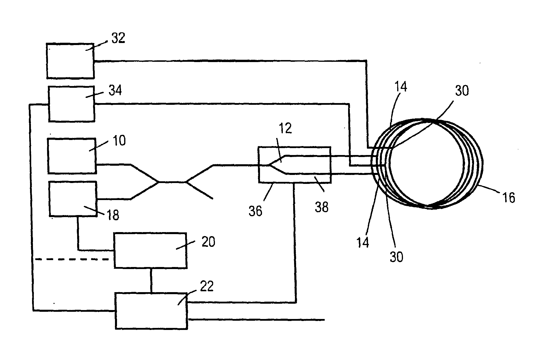
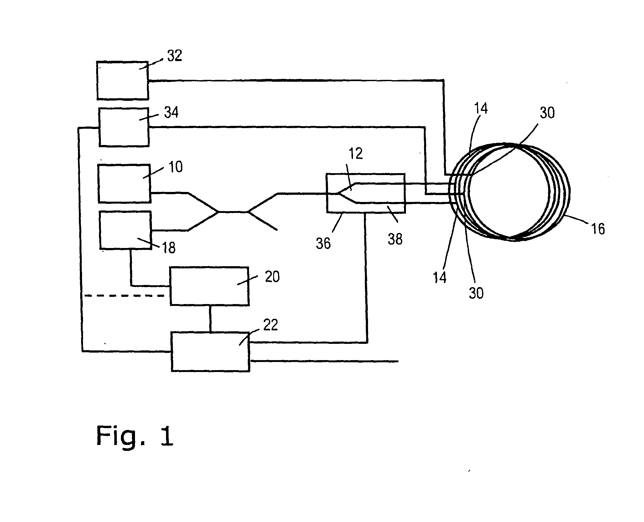
[0016]FIG. 1 is a schematic diagram of a first embodiment of a fiber optic interferometer in accordance with the invention. The fiber optic interferometer of FIG. 1 is a so-called Sagnac interferometer for determining a rotational speed acting on the arrangement. It has a first light source 10, the output beam of which is directed to a coupler 12 that can act as a beam splitter as well as a coupler depending on the direction of the light beam. In the coupler 12, the light beam coming from the first light source 10 is split into two partial light beams that are radiated in opposite directions into an optical fiber 14. The optical fiber 14 is wound on a carrier (not illustrated) to form a fiber coil 16. After passing through the optical fiber 14, the two partial light beams propagating in opposite directions are combined to form a light beam in the coupler 12. The light beam produced by superimposition of the two partial light beams is directed to a first photodetector 18, the output ...


PUM


Abstract

A fiber-optic interferometer comprising an optical fiber wound to form a fiber coil into which two partial light beams of a first light source can be coupled. The Bragg structure is integrated into the fiber coil. Said Bragg structure comprises an optical fiber having a periodically varying refractive index. In a method for determining physical state parameters in the interior of a fiber coil of a fiber optic interferometer information about physical state parameters in the interior of the fiber coil is obtained on the basis of the reflection wavelength of a Bragg structure comprising an optical fiber having a periodically varying refractive index is integrated into the fiber coil.

Description

BACKGROUND[0001]1. Field of the Invention[0002]The present invention relates to a fiber optic interferometer and a method for determining physical state parameters in the interior of the coil of a fiber optic interferometer.[0003]2. Description of the Prior Art[0004]Fiber optic interferometers are employed, inter alia, for measuring rotational speeds. To accomplish this, a light beam is split into two partial beams, guided in opposite directions in a circle, to meet one another again after one or more circulations. The interference pattern of the two superimposed partial beams changes if the fiber optic interferometer is rotated about an axis perpendicular to the beam plane, as the optical paths of the two partial beams are no longer of equal lengths.[0005]The resulting interference pattern is not only a function of rotational speed, but may also depend on external parameters such as temperature. Since fiber optic interferometers are employed worldwide today over a wide range of app...

Claims


Application Information

Patent Timeline
Patent Type & Authority Applications(United States)
IPC IPC(8): G01B9/02
CPCG01C19/721
Inventor DORNER, GEORG
Owner NORSROP GRUMAN LITEF GMBKH
Why Eureka
Try Eureka