Method of connecting busbars with capacitor and product manufactured by the same method

Inactive Publication Date: 2011-06-23
NUINTEK
View PDF3 Cites 28 Cited by
  • Summary
  • Abstract
  • Description
  • Claims
  • Application Information

AI Technical Summary

Benefits of technology

Therefore, it is an object of the present invention to provide a method of to connecting busbars with different polarity for a capacitor and a product manufactured by the same method, to improve the inductance of the capacitor by maximizing the area overlapped by the busbars, to prevent insulation capability from decreasing in severe environments when inserting an insulating material between the busbars, to increase the productivity by improving the troublesome work of inserting the insulating material, to greatly improve the electrical characteristics and reliability of the capacitor by decreasing the inductance, and to prolong the life of the capacitor.
In accordance with an embodiment of the present invention, there is provided a method of connecting busbars for a capacitor which is manufactured by connecting an N-pole busbar and a P-pole busbar, each of which has different polarity, to both thermal sprayed surfaces of a plurality of capacitor devices, conne

Problems solved by technology

However, in case of high-inductance, high-voltage in use, a flow of a great amount of current, or high-frequency, peripheral components of the capacitor are affected and heat is generated in the capacitor by serge voltage.
The heat generated in the capacitor deteriorates the electrical characteristics of the capacitor, shortens the life time of the capacitor and decreases the reliability of the performance of the capacitor.
However, since the area overlapped by the N-pole and P-pole busbars is small, there is

Method used


Image

  • Method of connecting busbars with capacitor and product manufactured by the same method
  • Method of connecting busbars with capacitor and product manufactured by the same method
  • Method of connecting busbars with capacitor and product manufactured by the same method

Examples


embodiment

Preferred Embodiment

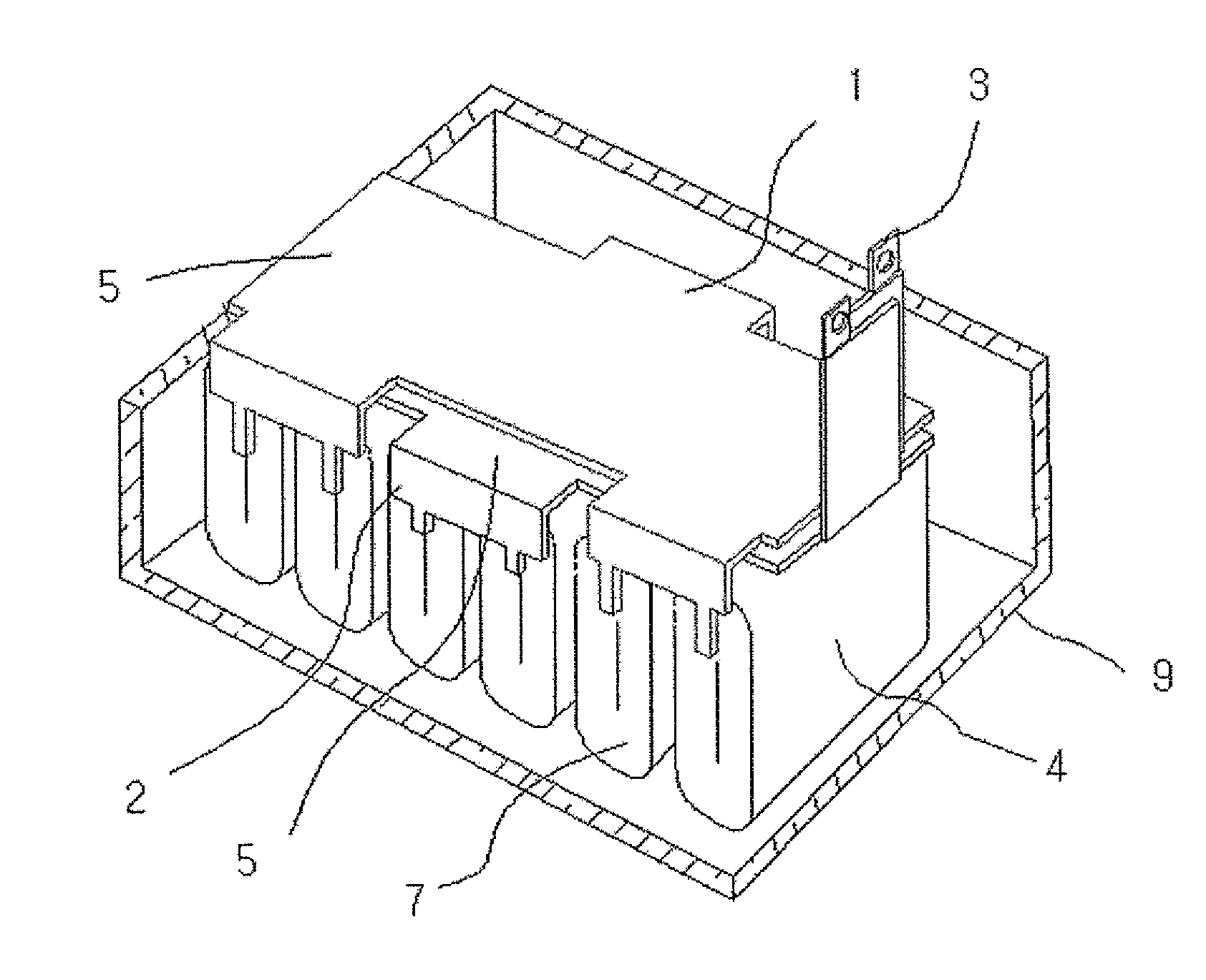
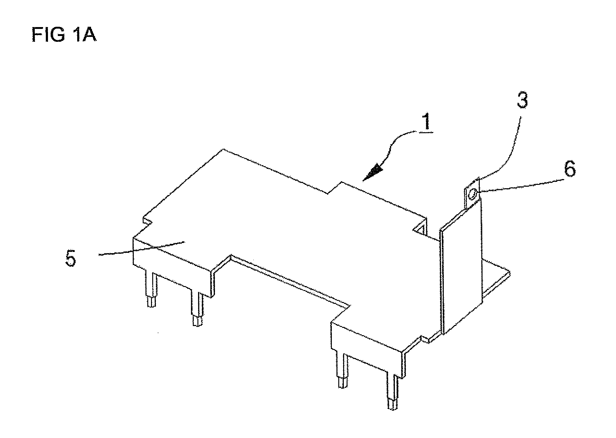
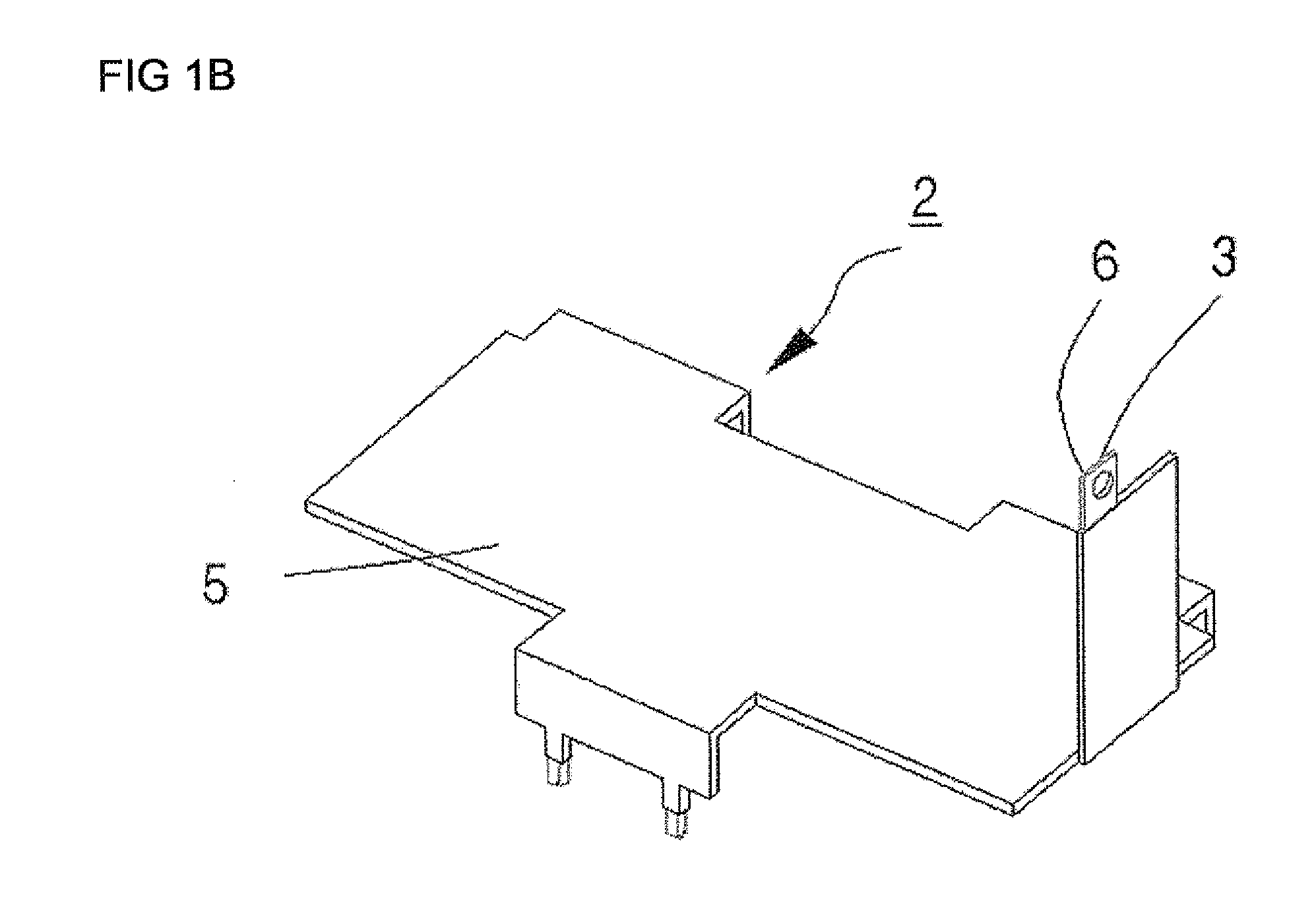
As illustrated in FIG. 1C, at least parts of an N-pole busbar 1 and a P-pole busbar 2, each of which has different polarity, are coated with an insulating material 5, such as epoxy, to be provided with insulation capability. The N-pole busbar 1 and the P-pole busbar 2 are connected so that at least parts of the N-pole busbar 1 and P-pole busbar 2 overlap each other. The interaction of the overlapped busbars decreases the inductance of the capacitor, improves the insulation capability and increases the productivity by improving the workability.

The N-pole busbar 1 and the P-pole busbar 2 connected to the capacitor devices in a zigzag shape so that the N-pole busbar and the P-pole busbar are alternated on each side surface 7 (thermal spray surface) of capacitor assembly.

In other modified embodiments, an N-pole busbar 1 and a P-pole busbar 2 may be coated with an insulating material 5, such as urethane, they may be injection-coated with an insulator, such as plastic,...


PUM

PropertyMeasurementUnit
Temperatureaaaaaaaaaa
Electrical inductanceaaaaaaaaaa
Capacitanceaaaaaaaaaa

Abstract

There is provided a method of connecting busbars for a capacitor and a product manufactured by the same method, whereby the inductance of the capacitor is decreased and thus the amount of heat generated in the capacitor is decreased to improve the temperature characteristics and electrical characteristics of the capacitor and the reliability of the quality of the capacitor, to consistently improve the insulation between the busbars having different polarity, and to maintain the insulation between the busbars in severe environments. The method of connecting busbars for a capacitor is characterized by coating at least parts of an N-pole busbar and a P-pole busbar, each of which has different polarity, with an insulating material; exposing parts of the N-pole and P-pole busbars outside an outer case so as to form a terminal to be connected to an other component; and connecting the N-pole busbar to the P-pole busbar in a manner that at least parts of the N-pole and P-pole is busbars overlap each other.

Description

BACKGROUND OF THE INVENTION1. Field of the InventionThe present invention relates to a method of connecting busbars with capacitors to improve the performance of a capacitor, and more particularly, to a method of connecting busbars with capacitors, to improve the temperature characteristics and performance of the capacitor and the reliability of quality of the capacitor by decreasing the inductance of the capacitor to drop the surge voltage of an inverter and therefore decreasing the amount of heat generated in the capacitor.2. Description of the Related ArtIn general, case-molded type capacitor for electrical devices, phase advancers and electronic devices, among others, are widely used in various industrial fields.In these capacitors, plastic films are used as dielectric materials. The plastic films may include plastic films, such as polyethylene terephthalate (PET) resin, polypropylene (PP) resin, polyethylene naphthalate (PEN) resin, polycarbonate (PC) resin and polyphenylene su...

Claims


Application Information

Patent Timeline
IPC IPC(8): H01G4/38H01G4/00
CPCH01G4/228Y10T29/43H01G4/38
Inventor YANG, CHANG-HOONPARK, DAE-JINJUN, YONG-WON
Owner NUINTEK
Why Eureka
Try Eureka