
Ac-to-dc converting circuit applicable to power-charging module

a technology of converting circuit and power-charging module, which is applied in the direction of electric variable regulation, process and machine control, instruments, etc., can solve the problems of large output ripple current, disadvantages of transformers based on half-bridge conversion, and inability to use as power-charging modules for electric vehicles. , to achieve the effect of reducing the number of current measuring elements and the cost of the transformer

Inactive Publication Date: 2011-06-23
IND TECH RES INST
View PDF4 Cites 32 Cited by
  • Summary
  • Abstract
  • Description
  • Claims
  • Application Information

AI Technical Summary

Benefits of technology

This patent describes an AC-to-DC converting circuit that uses an immittance conversion circuit for voltage to current conversion. This circuit simplifies the control mechanism of a power-charging module, reduces the number of current measuring elements, and lowers the cost. The circuit includes an input filter, input full-bridge rectifier, inverter, immittance conversion circuit, high-frequency transformer, and output full-bridge rectifier. The high-frequency transformer transforms the AC voltage generated by the inverter into an AC voltage with various intensities. The output full-bridge rectifier rectifies the transformed AC voltage into a DC voltage.

Problems solved by technology

The single-staged converter is advantageous in its simple configuration and thus low cost, but it results in large output ripple current and is thus not suitable for use as a power-charging module for electric vehicles.
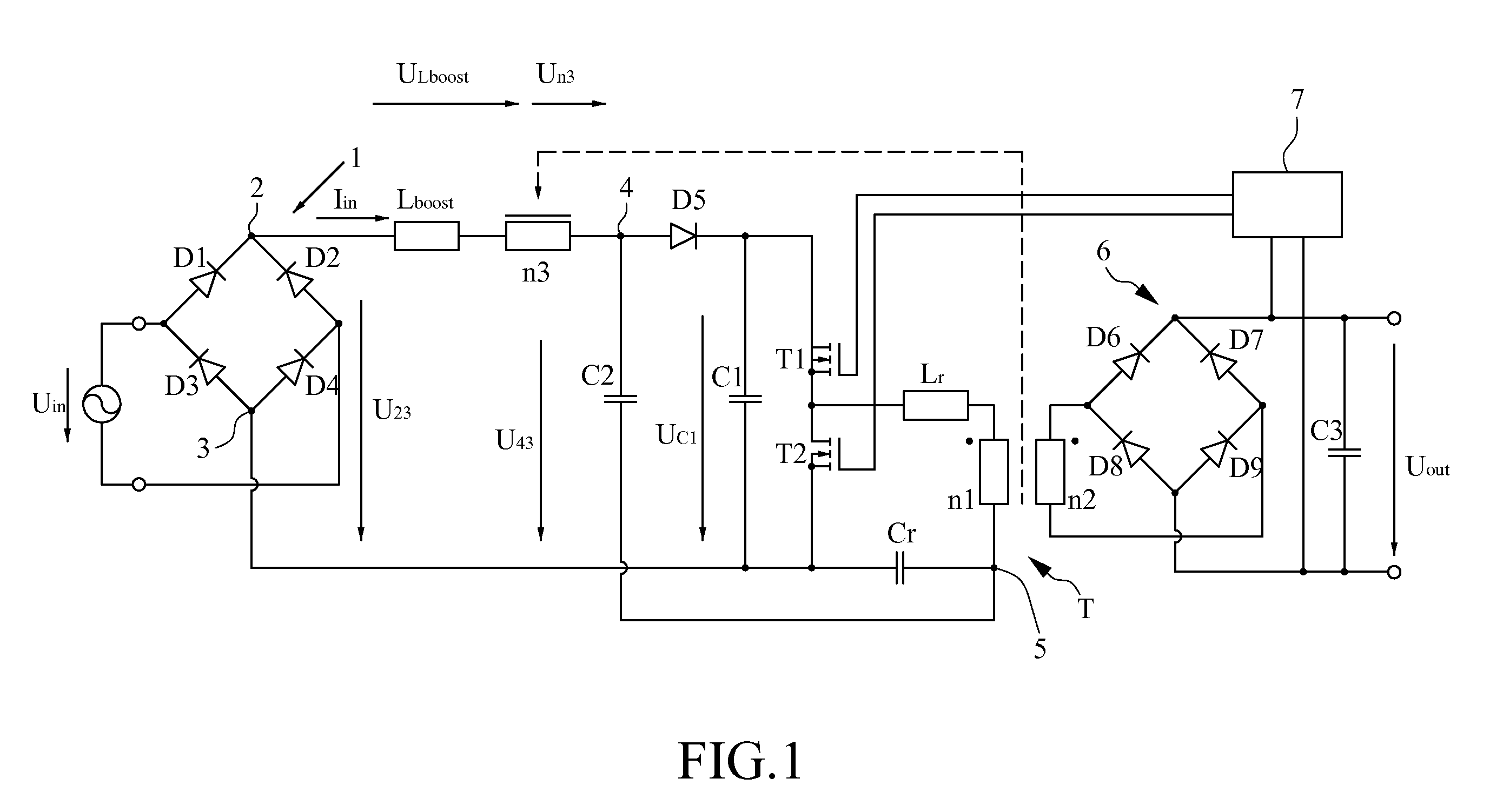
The transformer based on half-bridge conversion has disadvantages such as large size and heavy weight, as shown in FIG. 1.
Moreover, the demand in voltage resistance for the switches T1 and T2 is very high, which leads to lower conversion efficiency and higher manufacturing cost.
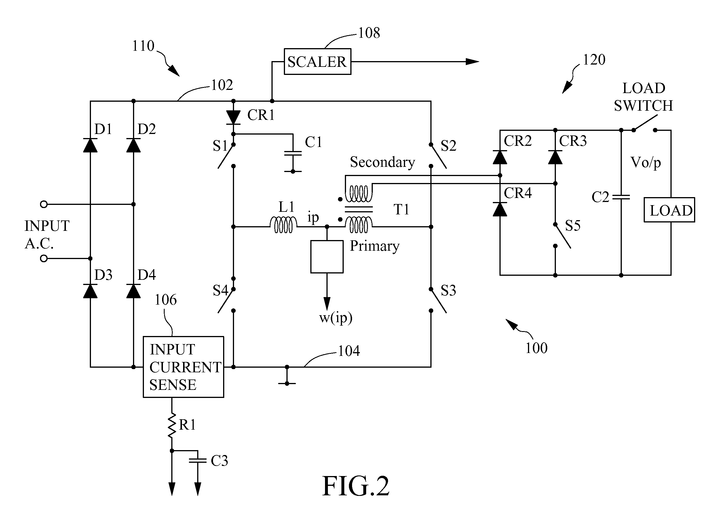
The circuit configurations in FIG. 2 and FIG. 3 are disadvantageous for large number of active switches and current sensors, resulting in higher manufacturing cost.

Method used


Image

  • Ac-to-dc converting circuit applicable to power-charging module
  • Ac-to-dc converting circuit applicable to power-charging module
  • Ac-to-dc converting circuit applicable to power-charging module

Examples


Embodiment Construction

[0013]The disclosure can be exemplified by but not limited to the embodiment as described hereinafter.

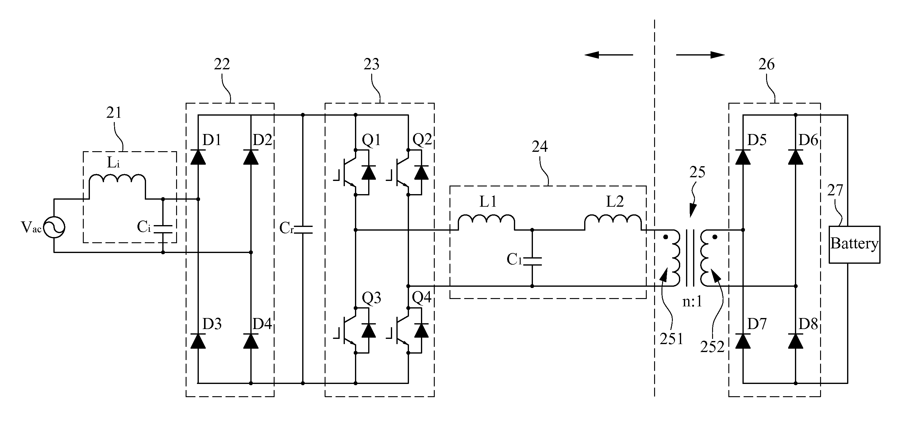
[0014]Please refer to FIG. 4, which is a circuit diagram of an AC-to-DC converting circuit in this disclosure. More particularly, FIG. 5 is a detailed circuit layout of FIG. 4, which is suitable for use as a power-charging module for electric vehicles. The AC-to-DC converting circuit applicable to a power-charging module comprises two parts such as a first stage being a low-frequency AC to high-frequency AC converter comprising an input filter 21, an input full-bridge rectifier 22, an inverter 23 and an immittance conversion circuit 24 and a second stage being an AC-to-DC converter comprising a single-phase high-frequency transformer 25 and a full-bridge rectifier 26. These elements are described herein.

[0015]The input filter 21 comprises an inductor (Li) and a capacitor (Ci) and is capable of filtering out harmonic components of an input AC voltage Vac. The output terminal of the i...


PUM


Abstract

The AC power generated by AC utility has been successfully transferred from AC-to-DC by means of an AC-to-DC converting circuit. This disclosure provides an AC-to-DC converting circuit applicable to a power-charging module, and the AC-to-DC converting circuit comprises two parts such as a first stage being a low-frequency AC to high-frequency AC converter comprising an input full-bridge rectifier, a full-bridge inverter and an immittance conversion circuit and a second stage being an AC-to-DC converter comprising a single-phase transformer and a full-bridge rectifier, where the inverter in the first stage is switched at high frequencies so as to reduce the size of the transformer in the second stage. Additionally, the immittance conversion circuit is further characterized in voltage to current conversion so as to simplify the control mechanism of the power-charging module, reduce the number of current measuring elements and the cost thereof.

Description

1. TECHNICAL FIELD[0001]The disclosure generally relates to an AC-to-DC converting circuit and, more particularly, to an AC-to-DC converting circuit using an immittance conversion circuit for voltage to current conversion so as to simplify the control mechanism of a power-charging module, reduce the number of current measuring elements and the cost thereof.2. TECHNICAL BACKGROUND[0002]With the increase in oil price and the trend of eco-conscious, people have started to worry about the green house effect due to increasing emission of carbon dioxide. Therefore, the demand of clean and environment-friendly energies grows rapidly. The development of electric vehicles and power-charging modules has become a trend that will make the earth healthier. In order to prevent current leakage from rechargeable batteries during charging, a transformer is required to be added to the power-charging module. The power-charging modules can be categorized into high-frequency isolated power-charging modu...

Claims


Application Information

Patent Timeline
Patent Type & Authority Applications(United States)
IPC IPC(8): H02M3/335
CPCB60L11/1811H02J7/025Y02T90/14Y02T10/92Y02T90/127Y02T10/7005Y02T10/7072B60L53/20H02J7/02H02J7/00712Y02T10/70H02J5/00Y02T90/12
Inventor HO, YEH-HSIANGKONISHI, YOSHIHIROHUANG, YI-SHUO
Owner IND TECH RES INST
Learn More