Optical integrated circuit

a technology of integrated circuits and optical components, applied in the direction of optical light guides, optical waveguide light guides, instruments, etc., can solve the problem that adiabatic rotators may not be adequately integrated onto a pic having reduced dimensions

Active Publication Date: 2011-06-23
INFINERA CORP
View PDF4 Cites 19 Cited by
  • Summary
  • Abstract
  • Description
  • Claims
  • Application Information

AI Technical Summary

Problems solved by technology

Accordingly, adiabatic rotators may not be adequately integrated onto a PIC having reduced dimensions.

Method used


Image

  • Optical integrated circuit
  • Optical integrated circuit
  • Optical integrated circuit

Examples


Embodiment Construction

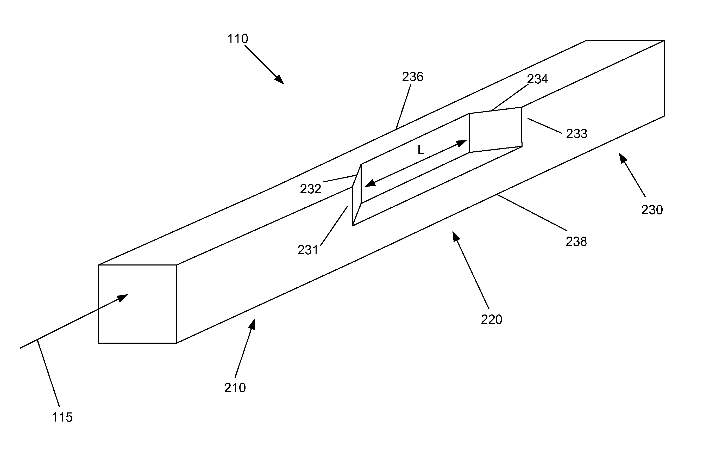
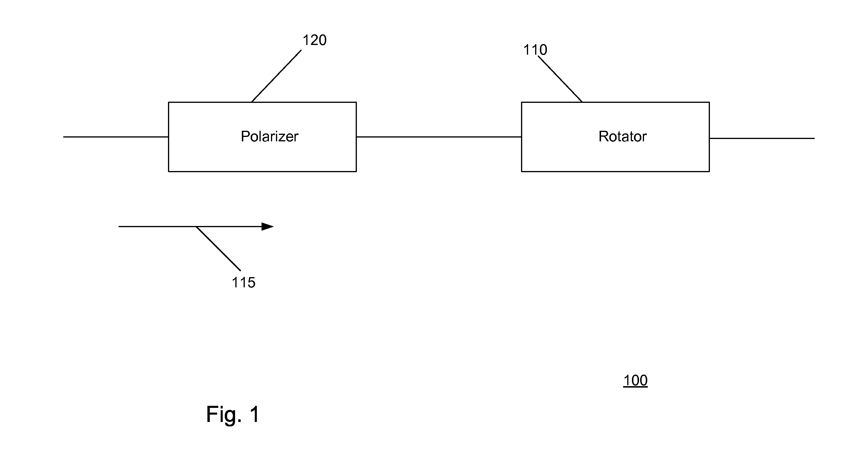
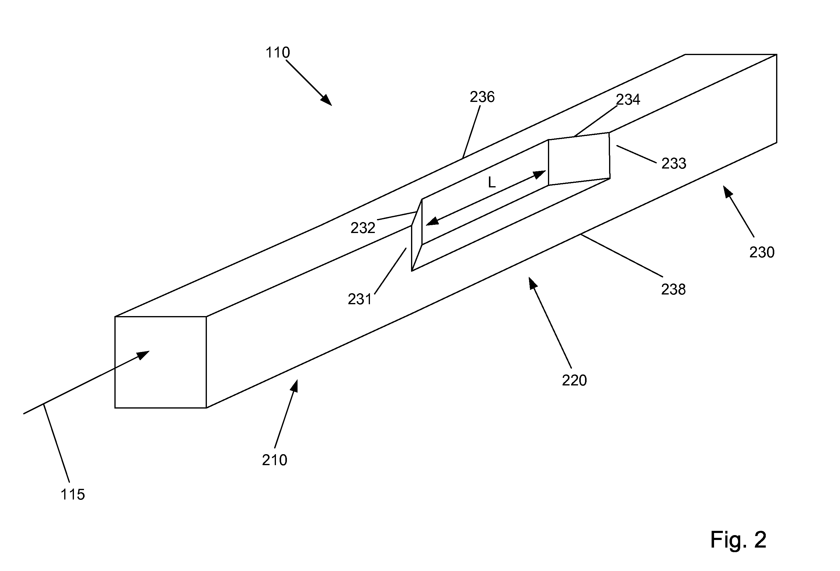
[0016]Consistent with the present disclosure, an optical integrated circuit is provided that includes a non-adiabatic polarization rotator that rotates the polarization of an incoming optical signal over a relatively short length. Light is supplied to the polarization rotator via a polarizer, which insures that the optical input to the polarization rotator has a desired polarization. Preferably, the polarization rotator has a structure that is readily implemented with semiconductor materials and can be fabricated with known processing techniques. In addition, the polarization rotator and polarizer may include similar materials and / or layers, such that both may be readily integrated on a common substrate, such as an indium phosphide (InP) substrate.

[0017]Reference will now be made in detail to the present exemplary embodiments, examples of which are illustrated in the accompanying drawings. Wherever possible, the same reference numbers will be used throughout the drawings to refer to...


PUM


Abstract

Consistent with the present disclosure, a non-adiabatic polarization rotator is provided that can rotate the polarization of an incoming over a relatively short length. Light is supplied to the polarization rotator via a polarizer, which insures that the optical input to the polarization polarization rotator has a desired polarization. Preferably, the polarization rotator has a structure that is readily implemented with semiconductor materials and can be fabricated with known processing techniques. In addition, the polarization rotator and polarizer may include similar materials and/or layers, such that both may be readily integrated on a common substrate, such as an indium phosphide (InP) substrate.

Description

BACKGROUND[0001]An electromagnetic wave, such as a light wave, has an associated vector field that has two primary and orthogonal polarization states or vector directions. When referring to the propagation of light in a waveguide provided on a substrate, these polarization states are generally referred to as the Transverse Electric (TE) mode and Transverse Magnetic (TM) mode. In the TM mode, the electric field of the light wave is oriented perpendicular to the substrate on which the waveguide sits, while in the TE mode the electric field is oriented parallel to the substrate.[0002]Optical components, referred to as polarization rotators, can rotate the polarization of an optical signal, for example, from a TE mode to a TM mode. As generally understood, many rotators are made of a birefringent material, whereby the refractive index of such material along one polarization direction or birefringent axis is different than the refractive index in a different polarization direction or bir...

Claims


Application Information

Patent Timeline
Patent Type & Authority Applications(United States)
IPC IPC(8): G02B6/126
CPCG02B6/126G02B6/2766G02B6/2706G02B6/27
Inventor NAGARAJAN, RADHAKRISHNAN L.KATO, MASAKILAL, VIKRANT
Owner INFINERA CORP
Why Eureka
Try Eureka