
Eureka
For R&D, Eureka makes reading and utilizing patents & technical documents easy.
Eureka AIR
Designed for self-driven R&D workflows. Generate viable solutions, solve complex R&D challenges, empower your innovation with AI.

Eureka Materials
Designed for material experts only. Revolutionize your material R&D, from search, analyze, to developing new materials.

TechResearch
Generate reliable direction feasibility study reports for your R&D in just a few steps.

TechSeek
Discover and master advanced knowledge NOW. Basics, ideas, possibilities, all at once.

TechMind
As an expert in R&D Theories, TechMind can generates customized viable solutions instantly.

TechRisk
Analyze your overall solution with one click, know your potential R&D risks in advance.

TechMonitor
Get weekly tech updates, stay abreast of the latest tech innovations and key insights.
Fuel cell system and fuel cell status detection method
- Summary
- Abstract
- Description
- Claims
- Application Information
AI Technical Summary
Benefits of technology
Problems solved by technology
Method used
Image

Examples
first embodiment
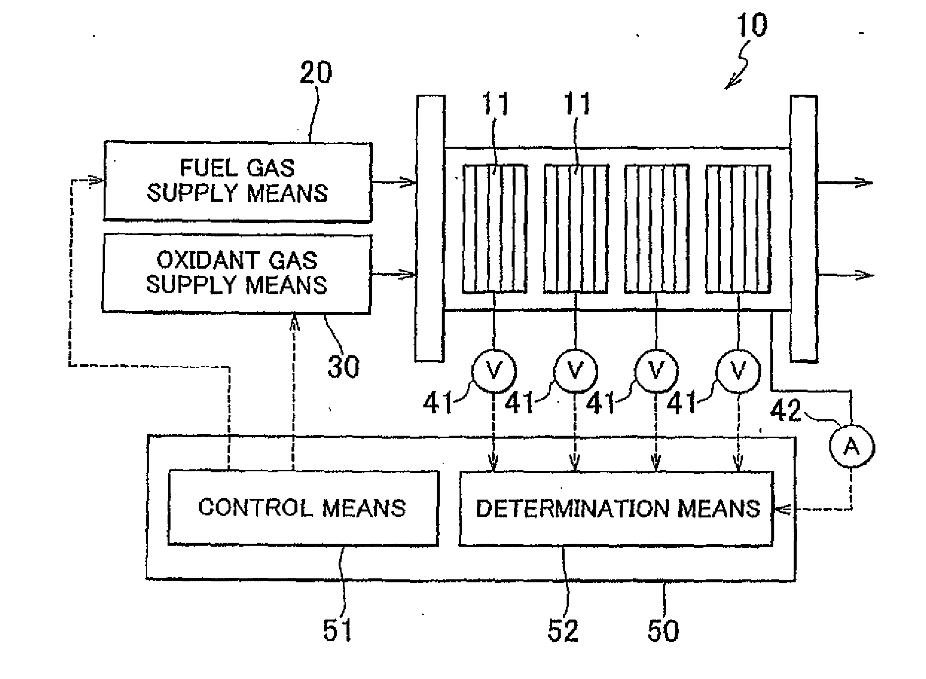
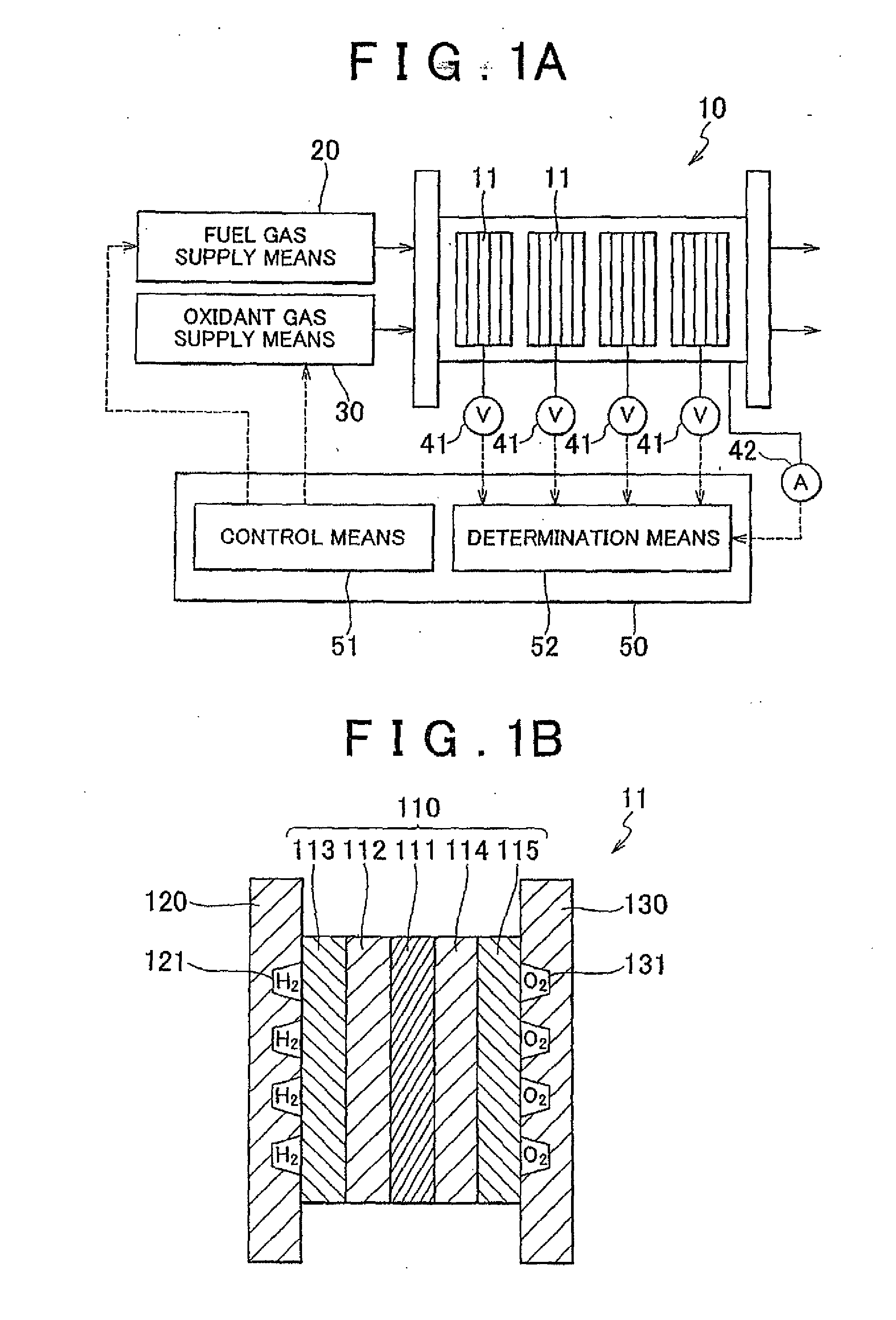
[0039]FIG. 1 is a drawing for explaining a fuel cell system 100 of a first embodiment of the invention. FIG. 1A is a schematic diagram showing the overall configuration of the fuel cell system 100. FIG. 1B is a schematic cross-sectional view of. a cell 11 to be subsequently described. As shown in FIG. 1A, the fuel cell system 100 is provided with a fuel cell stack 10, fuel gas supply means 20, oxidant gas supply means 30, voltage detection means 41, current detection means 42 and a processing unit 50.
[0040]The fuel cell stack 10 has a structure in which one or a plurality of cell groups are laminated, and one or a plurality of cells 11 are laminated in each cell group. As shown in FIG. 1B, the cells 11 have a structure in which a membrane electrode assembly 110 is interposed between a separator 120 and a separator 130. In the membrane electrode assembly 110, an anode catalyst layer 112 and a gas diffusion layer 113 are bonded to an electrolyte membrane 111 in that order on the side ...
PUM
 Abstract
Description
Claims
Application Information
 - R&D Engineer
- R&D Manager
- IP Professional
- Industry Leading Data Capabilities
- Powerful AI technology
- Patent DNA Extraction
Browse by: Latest US Patents, China's latest patents, Technical Efficacy Thesaurus, Application Domain, Technology Topic, Popular Technical Reports.
© 2024 PatSnap. All rights reserved.Legal|Privacy policy|Modern Slavery Act Transparency Statement|Sitemap|About US| Contact US: help@patsnap.com