Blood-pressure sensor, manufacturing method thereof, and blood-pressure sensor system

a blood pressure sensor and manufacturing method technology, applied in the field of blood pressure sensors, can solve the problems of insufficient reliability of accuracy, easy arrangement of sensors, and fear of blood clot generation or injury to the blood-vessel wall

Inactive Publication Date: 2011-06-23
OLYMPUS CORP +1
View PDF0 Cites 12 Cited by
  • Summary
  • Abstract
  • Description
  • Claims
  • Application Information

AI Technical Summary

Benefits of technology

[0011]Advantage of the invention will be set forth in the description which follows, and in part will be obvious from the description, or may be learned by practice of the invention. Advantages of the invention may be realized and obtained by means of the instrumentalities and combinations particularly pointed out hereinafter.
[0012]The accompanying drawings, which are incorporated in and constitute a part of the specification, illustrate embodiments of the invention, and together with the general description given above and the detailed description of the embodiments given below, serve to exp

Problems solved by technology

In the proposals made so far, the sensor is fixed to the blood-vessel wall, and measurement is invasively carried out, and hence generation of a blood clot or injury to the blood-vessel wall is feared.
However, when the cuff is actually u

Method used


Image

  • Blood-pressure sensor, manufacturing method thereof, and blood-pressure sensor system
  • Blood-pressure sensor, manufacturing method thereof, and blood-pressure sensor system
  • Blood-pressure sensor, manufacturing method thereof, and blood-pressure sensor system

Examples


Embodiment Construction

[0022]Hereinafter, an embodiment of the present invention will be described below in detail with reference to the drawings.

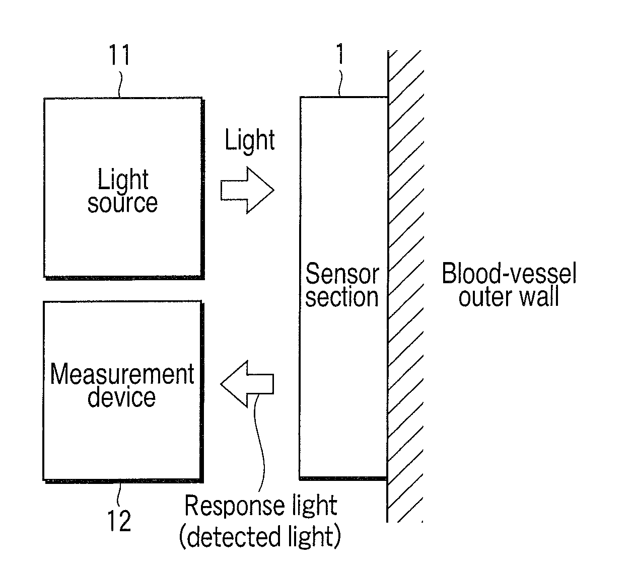
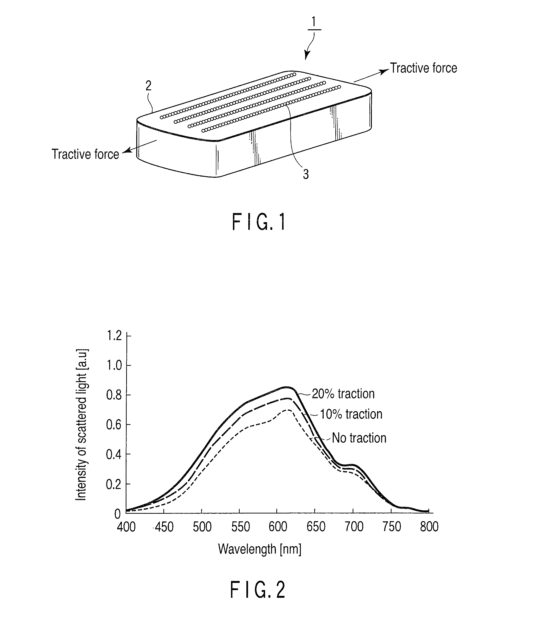
[0023]In FIG. 1, the external configuration of a sensor section used for a blood-pressure sensor of an embodiment according to the present invention is shown.

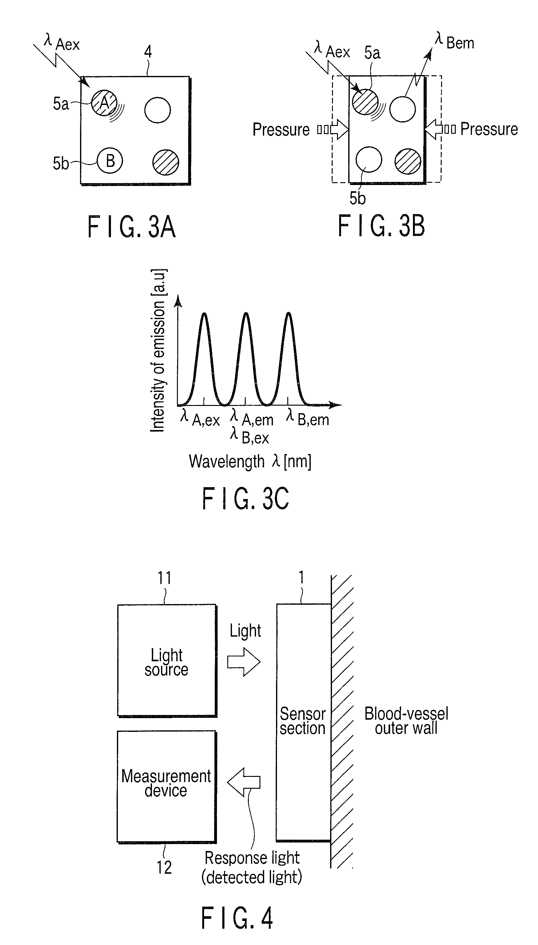
[0024]The sensor section 1 is constituted of an elastic body 2 previously having a predetermined elastic coefficient, and a plurality of particles (particle body) 3 fixed to the surface of the elastic body 2 in line in a pattern to be described later or dispersedly contained in the elastic body 2. In the sensor section 1, distances between particles are changed by tractive force or pressure (pressing force) applied at both ends or at one end thereof.

[0025]The elastic body 2 has, in this embodiment, a shape of a rectangular parallelepiped, and as an elastic body material, a silicon series elastic body (silicon elastomer) such as polydimethylsiloxane (PDMS) or the like is used. It should be noted that when as...


PUM


Abstract

A blood-pressure sensor is constituted of an elastic body which is fitted to a blood-vessel outer wall, and a shape of which is deformed by force generated by pulsing motion of expansion and contraction of the blood vessel, and a plurality of nanosized particles dispersedly provided in the elastic body, and when the force is applied to the sensor in a state where the sensor is irradiated with light, the magnitude of the force is measured on the basis of intensity of scattered light from the particles or emission intensity of fluorescence from the particles, the intensity of the scattered light or emission intensity of the fluorescence corresponding to a change in distance between the particles.

Description

CROSS-REFERENCE TO RELATED APPLICATIONS[0001]This application is based upon and claims the benefit of priority from prior Japanese Patent Application No. 2009-291274, filed Dec. 22, 2009, the entire contents of which are incorporated herein by reference.BACKGROUND OF THE INVENTION[0002]1. Field of the Invention[0003]The present invention relates to a blood-pressure sensor to which a dynamic sensor for optically measuring dynamical characteristics of an object such as displacement and force is applied, and which is configured to measure intravascular pressure from the displacement of the blood vessel, manufacturing method thereof, and blood-pressure sensor system.[0004]2. Description of the Related Art[0005]In general, as a blood-pressure monitoring method associated with blood vessel disease such as a congestive heart disease, arteriosclerosis, and the like, and a blood-pressure monitoring method to be employed after replacement of a vessel with an artificial blood vessel, an implan...

Claims


Application Information

Patent Timeline
IPC IPC(8): A61B6/00
CPCA61B5/021A61B2562/0266A61B5/6826
Inventor SHIMOYAMA, ISAOMATSUMOTO, KIYOSHIKAN, TETSUOIWASE, EIJIKOYAMA, ASUTOAJIKI, YOSHIHARU
Owner OLYMPUS CORP
Why Eureka
Try Eureka