Switched protective device against electromagnetic interference

a technology of electromagnetic interference and protective device, which is applied in the field of devices and methods for working in the presence of electromagnetic fields, can solve the problems of short operating period of equivalent energy reserves, increased complexity of the overall system, and increased risk of medical devices or implantable medical devices

Active Publication Date: 2011-06-23
BIOTRONIK SE & CO KG
View PDF16 Cites 29 Cited by
  • Summary
  • Abstract
  • Description
  • Claims
  • Application Information

AI Technical Summary

Benefits of technology

[0010]The object of one or more embodiments of the invention is to provide a device and a method for medical devices and implantable medical devices which eliminate the disadvantages of the prior art and allow safe operation in the presence of electromagnetic interference fields. The object is achieved by use of a medical device (MD) having the features as claimed herein.

Problems solved by technology

Besides MRI testing, however, other technical applications pose a risk to the user of medical devices or implantable medical devices, particularly when such applications generate strong electromagnetic interference fields (electromagnetic interference (EMI)) in their surroundings.
However, these technological approaches are not very specific, and create increased energy requirements which result in a shorter operating period for equivalent energy reserves.
Use of these optical lines prevents the injection of electromagnetic interference fields from an MRI device into the electrode lines, but the overall system is more complex since on the one hand the electrical signals must first be converted to optical signals, and on the basis of the signals the stimulation pulses must be generated from the optical signals at the stimulation site, and on the other hand signals that are measured at the stimulation site must likewise be converted.
As a rule, such higher-complexity systems also increase the energy requirements for an implant.
A disadvantage of this system is that for high RF fields it also allows heating of the electrodes, since the focus of the cited documents is on electromagnetic compatibility with metal detectors and electronic security units.

Method used


Image

  • Switched protective device against electromagnetic interference
  • Switched protective device against electromagnetic interference
  • Switched protective device against electromagnetic interference

Examples


Embodiment Construction

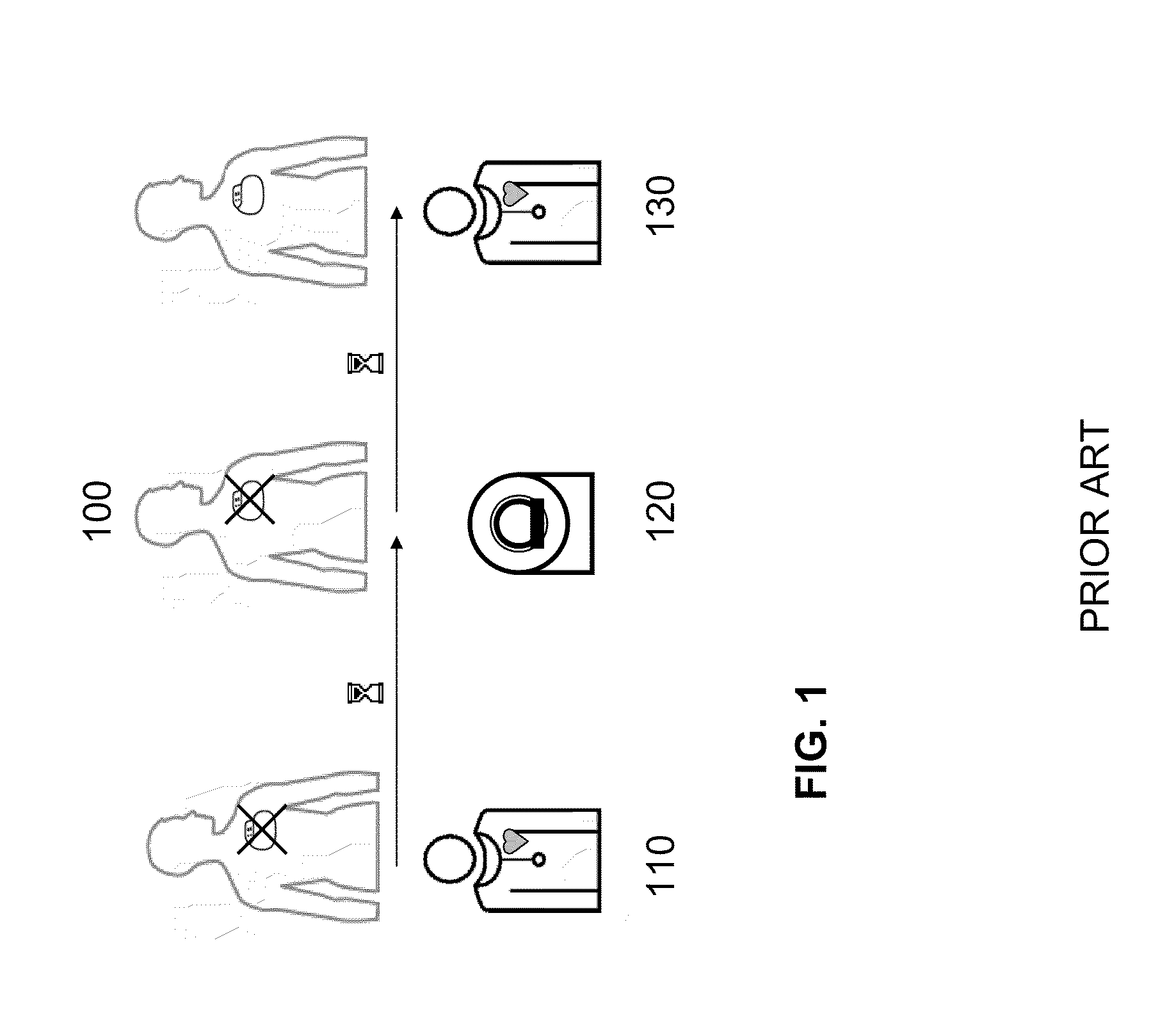
[0047]FIG. 1 describes the prior art, in which the ICD patient 100 receives follow-up care from a cardiologist before the planned MRT test, and the ICD is switched off 110. After a time delay of hours to days the MRT test is performed by a radiologist 120. After a further delay the patient is once again under the care of the cardiologist 130, and the ICD is switched back on. During the entire time from 110 to 130 the patient is without protection of the implanted defibrillator, and is essentially without rhythm monitoring. This residual risk is accepted in return for the benefits of the MRT test.

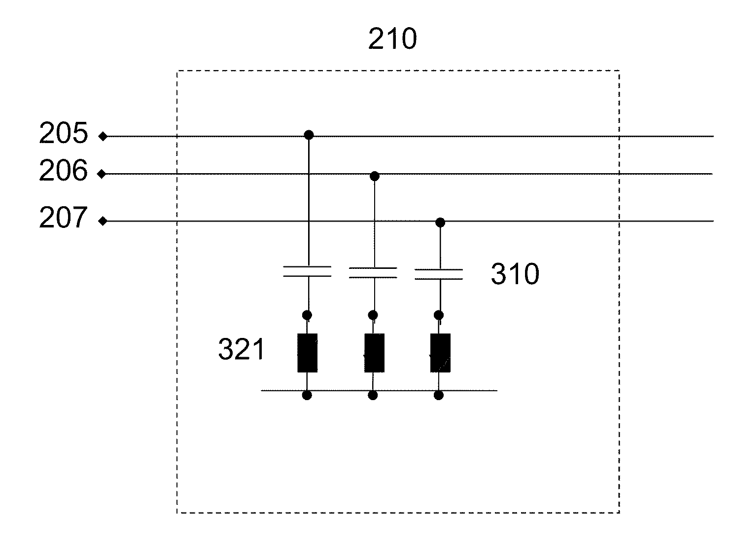
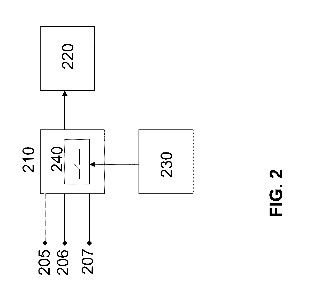
[0048]FIG. 2 shows a block diagram of the approach according to the invention, in which the incoming electrode lines (206 right ventricular, 205 right atrial, and 207 shock line for emitting high-energy pulses) are connected to the input protection circuit 210, and the characteristic of the input protection circuit 210 may be modified by a unit for detecting electromagnetic interference 230....


PUM


Abstract

A device and a method for working in the presence of electromagnetic fields, in particular fields occurring in magnetic resonance tomography (referred to below as “MRT” or “MRI”) imaging devices. More precisely, the invention relates to a medical device (MD) in which an electrode is in contact with bodily tissue, and for detection of electromagnetic interference fields the input characteristic of the MD is automatically modified by a switching device in such a way that the influences of the electromagnetic interference fields are minimized.

Description

[0001]This application claims the benefit of U.S. Provisional Patent Application 61 / 288,857, filed on Dec. 22, 2009, which is hereby incorporated herein by reference.BACKGROUND OF THE INVENTION[0002]1. Field of the Invention[0003]Embodiments of the invention relate to a device and a method for working in the presence of electromagnetic fields, in particular fields occurring in magnetic resonance tomography imaging devices. (“MRT” or “MRI” stand for magnetic resonance tomography and magnetic resonance imaging respectively, wherein these two acronyms are used interchangeably herein).[0004]2. Description of the Related Art[0005]Although MRI testing is becoming increasingly important in diagnostic medicine, it is contraindicated for some patients. Such contraindication may result from an active implanted medical device (also referred to below as “implant” or “IMD”). Besides MRI testing, however, other technical applications pose a risk to the user of medical devices or implantable medic...

Claims


Application Information

Patent Timeline
Patent Type & Authority Applications(United States)
IPC IPC(8): A61N1/08
CPCA61N1/37A61N1/3925A61N1/3718
Inventor DOERR, THOMASWEISS, INGO
Owner BIOTRONIK SE & CO KG
Why Eureka
Try Eureka