Heat or energy recovery housing and sealing system

a technology of energy recovery and ventilator, applied in the field of ventilation systems, can solve the problems of increasing stuffiness, poor air quality in the structure, and increasing the cost of ventilation, so as to reduce the leakage of the ventilation system, reduce the cost, and avoid the effect of affecting the operation of the ventilation system

Inactive Publication Date: 2011-06-30
AIR TECH EQUIP
View PDF3 Cites 14 Cited by
  • Summary
  • Abstract
  • Description
  • Claims
  • Application Information

AI Technical Summary

Benefits of technology

[0022]The disclosed housing and sealing system provides a strong, airtight seal between the energy and heat recovery core and its housing for use in a heat or energy recovery ventilator. The seal may be readily broken for removal of a core. This may be accomplished with minimal cost and without affecting the ventilation system in any other way.
[0023]When used in conjunction with a design which is designed to be as air tight as possible, the present housing and sealing system helps to ensure an airtight seal between the energy or heat recovery core and the supports. This helps reduce the leakage in the ventilation system and the contamination of the fresh supply airflow with return exhaust air.

Problems solved by technology

Such structures may experience poor air quality due to insufficient ventilation.
Within the structure, the indoor air may become stale, being increasingly stuffy, having high humidity levels and a build-up of indoor pollutants such as odours, mould and mildew, tobacco, chemical fumes and combustion by-products, and the like.
However, during the course of development and testing of heat and energy recovery ventilators, it has been discovered that an amount of leakage and contamination between the supply flow of fresh air and the exhaust flow of return air may be experienced, for example, between the cores and their supports within the housing.

Method used


Image

  • Heat or energy recovery housing and sealing system
  • Heat or energy recovery housing and sealing system
  • Heat or energy recovery housing and sealing system

Examples


Embodiment Construction

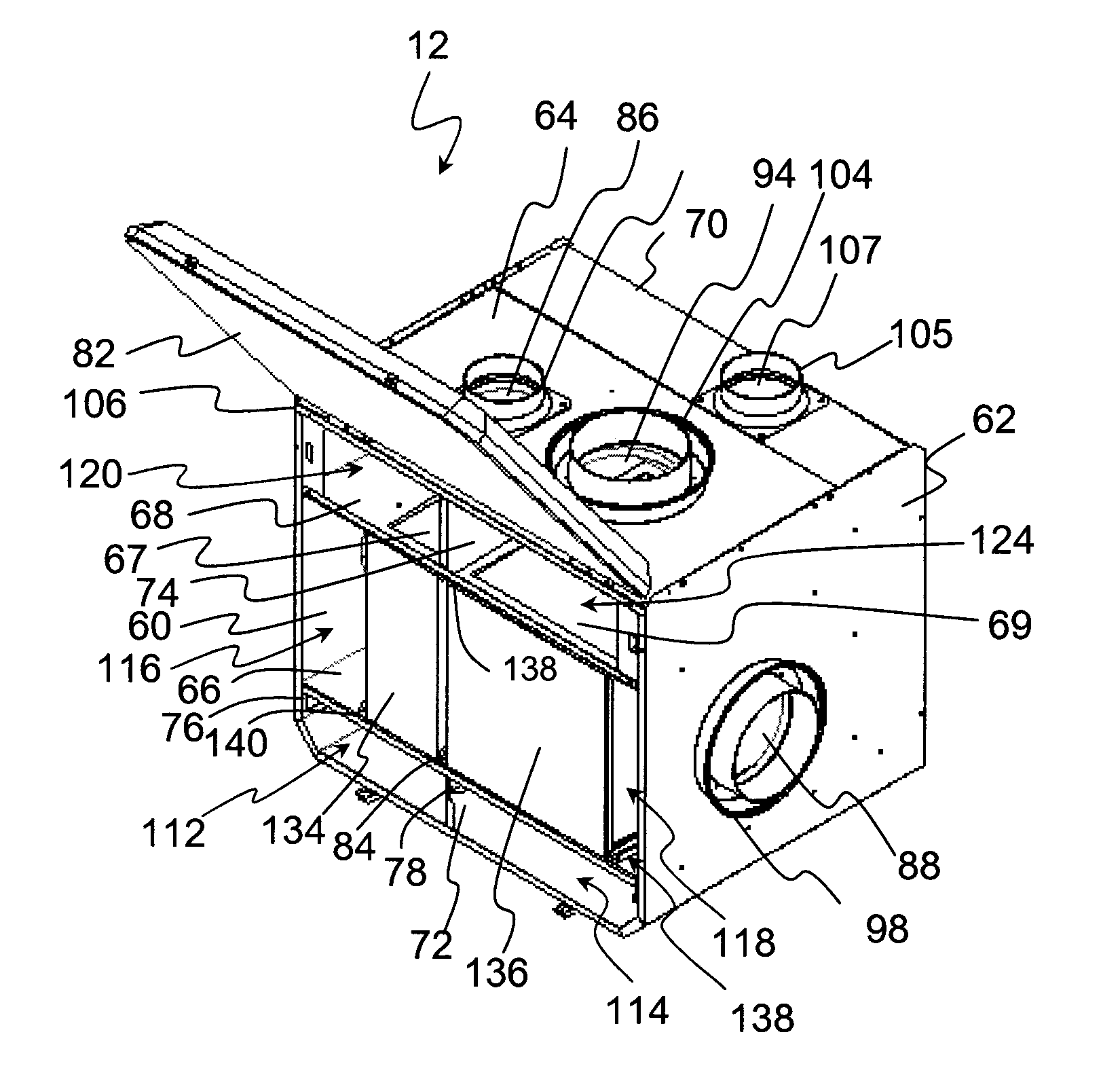
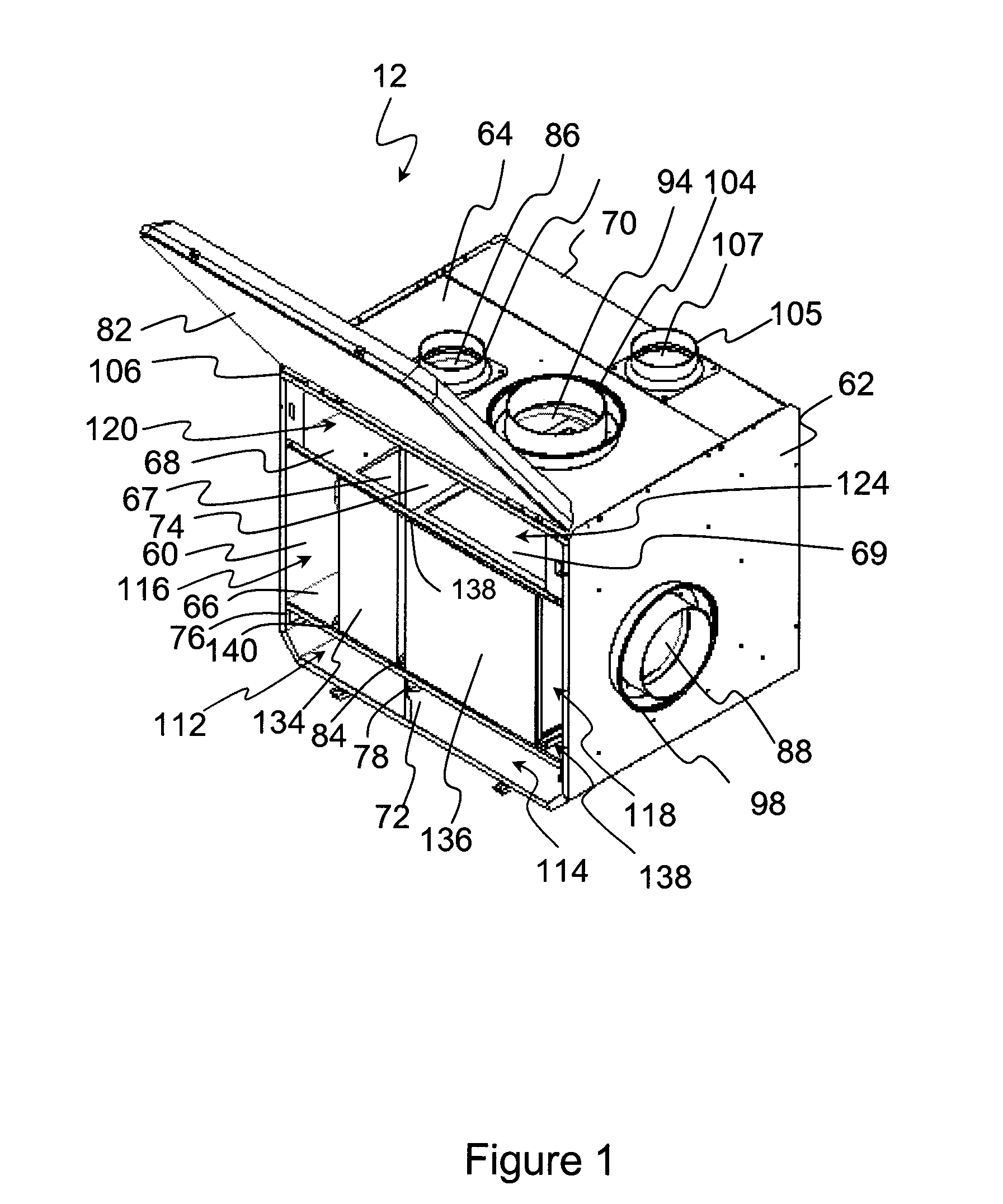
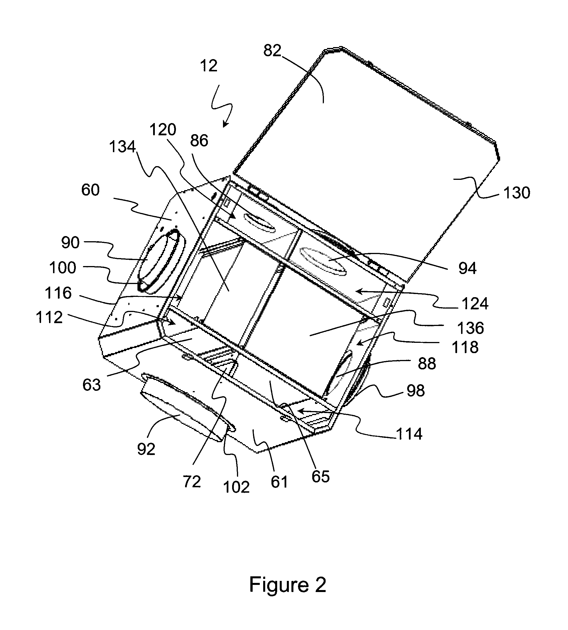
[0033]Reference will now be made in detail to some specific embodiments of the invention including the best modes contemplated by the inventors for carrying out the invention. Examples of these specific embodiments are illustrated in the accompanying drawings. While the invention is described in conjunction with these specific embodiments, it will be understood that it is not intended to limit the invention to the described embodiments. On the contrary, it is intended to cover alternatives, modifications, and equivalents as may be included within the spirit and scope of the invention as defined by the appended claims. In the following description, numerous specific details are set forth in order to provide a thorough understanding of the present invention. The present invention may be practiced without some or all of these specific details. In other instances, well known process operations have not been described in detail in order not to unnecessarily obscure the present invention....


PUM


Abstract

A heat and energy recovery ventilator housing comprising at least one means for releasable sealing engagement of the at least one energy core to the housing and for providing an air tight seal between the at least one energy core and an interior of the housing, said sealing means positioned to prevent a leakage between the supply airflow and the exhaust airflow, is described. A sealing system comprising a gasket having a sealing surface and a rail having contact surface, said gasket attachable to an interior of the ventilator housing and said rail attachable to the core at a location in alignment with the gasket, the gasket and the rail, when positioned in alignment, magnetically cooperating thereby forming an airtight seal for preventing an air leakage between the supply airflow and the return airflow within the housing but outside of the core is also described. The ventilator housing and sealing system allows for the easy insertion and removal of a heat or energy recovery ventilator core while maintaining an airtight seal when the core is in place.

Description

RELATED APPLICATION[0001]This application claims the benefit of Canadian Patent Application No. 2,596,146, filed Aug. 3, 2007.FIELD OF THE INVENTION[0002]The present invention relates to ventilation systems, more specifically, the present invention relates to a housing for an energy or heat recovery ventilator and to a sealing system therefor.BACKGROUND OF THE INVENTION[0003]Improvements in building construction standards, techniques and materials has led to the construction of well-insulated, more tightly built, leak-free structures. Such structures may experience poor air quality due to insufficient ventilation. Within the structure, the indoor air may become stale, being increasingly stuffy, having high humidity levels and a build-up of indoor pollutants such as odours, mould and mildew, tobacco, chemical fumes and combustion by-products, and the like. A ventilation system may be used for air exchange providing a continuous stream of fresh, outdoor air into a structure while exha...

Claims


Application Information

Patent Timeline
Patent Type & Authority Applications(United States)
IPC IPC(8): F28D17/00F16J15/53
CPCF24F13/30F24F12/00
Inventor BOUDREAU, PATRICK PAULLESTAGE, GEORGE ROBERT
Owner AIR TECH EQUIP
Why Eureka
Try Eureka