Aircraft fuselage frame in composite material with stabilized web

a composite material and stabilized web technology, applied in the direction of transportation and packaging, other domestic articles, efficient propulsion technologies, etc., can solve the problems of difficult to compete with machined metallic, and inability to meet the requirements of load frames. , to achieve the effect of reducing load requirements

Inactive Publication Date: 2011-06-30
AIRBUS OPERATIONS SL
View PDF6 Cites 16 Cited by
  • Summary
  • Abstract
  • Description
  • Claims
  • Application Information

AI Technical Summary

Benefits of technology

[0009]Another object of this invention is to provide an aircraft fuselage frame with stabilized web made of composite material whose configuration facilitates the manufacture thereof.
[0042]This provides an efficient procedure for manufacturing frame segments subject to lower load requirements.

Problems solved by technology

In the case of load frames, it is difficult to compete with machined metallic frames because, due to the high and differing stresses they must withstand, alternative frames in composite materials usually pose various manufacturing problems since their design is so complex.
One of the aforementioned problems is related to the attempt to achieve a frame design in which the webs are stabilized, thus making it possible to optimise the weight.
Although in the case of form frames there are now some proposals available, the same is not true of load frames in spite of the existing demand for them in the aeronautical industry.

Method used


Image

  • Aircraft fuselage frame in composite material with stabilized web
  • Aircraft fuselage frame in composite material with stabilized web
  • Aircraft fuselage frame in composite material with stabilized web

Examples


first embodiment

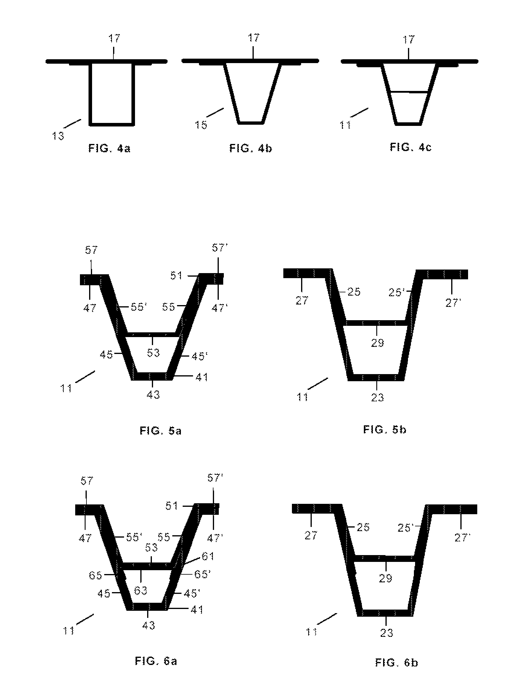
[0063]According to the manufacturing procedure under this invention, and as illustrated in FIGS. 5a and 5b, the first segment 31 of the frame with the cross section 11 is manufactured by joining an internal element 51 with closed omega-shaped section, formed by one head 53, two webs 55, 55′ and two feet 57, 57′, to an external element 41 with closed omega-shaped section, formed by one head 43, two webs 45, 45′ and two feet 47, 47′.

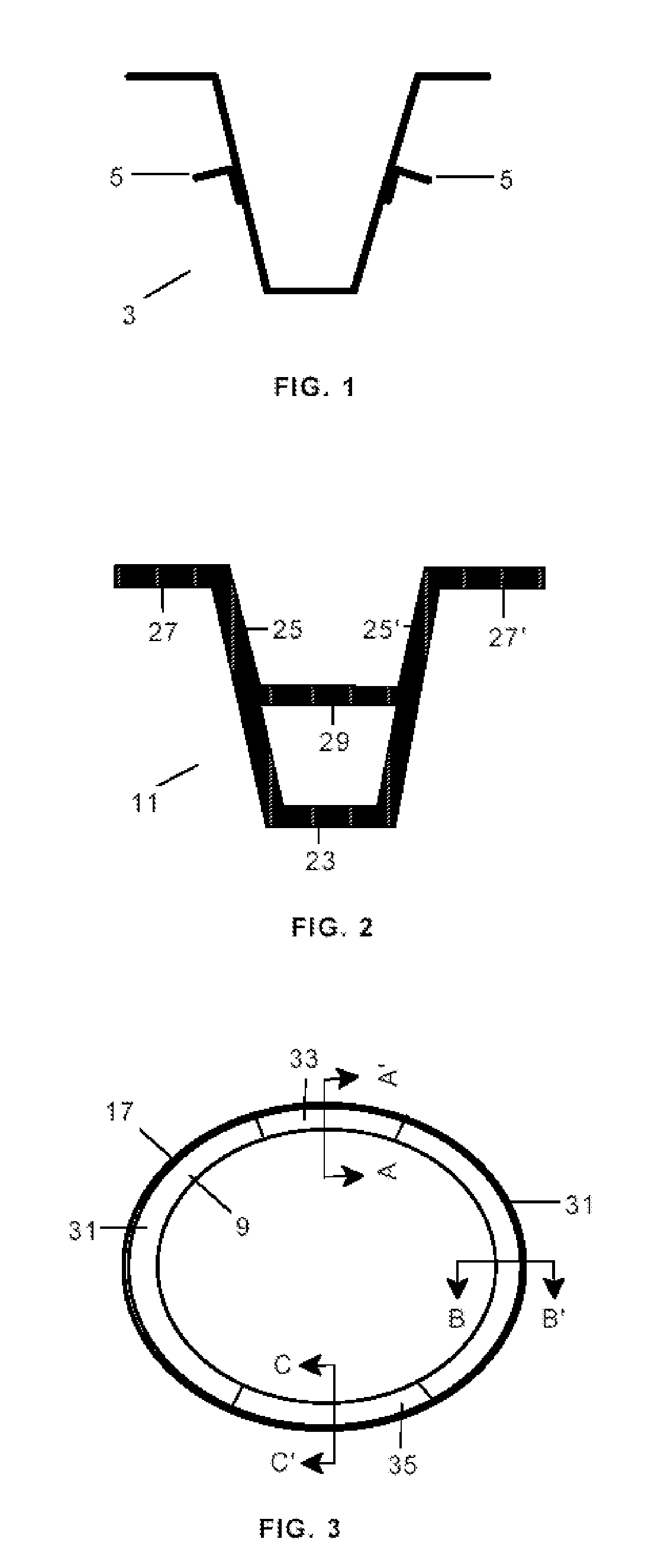
[0064]Thus the webs 25, 25′ of the resulting frame have a span with the thickness resulting from joining the webs 55, 55′ of the internal element 51 and the webs 45, 45′ of the external element 41, and another span with the thickness of the webs 45, 45′ of the external element 41. The feet 27, 27 of the resulting frame have the thickness resulting from joining the feet 57, 57′ of the internal element 51 and the feet 47, 47′ of the external element 41. Finally, the stiffening element 29 corresponds to the head 53 of the internal element 51. This cross secti...

second embodiment

[0065]According to the manufacturing procedure under this invention, and as illustrated in FIGS. 6a and 6b, the first segment 31 of the frame with the cross section 11 is manufactured using a third element 61 formed with layers of composite material to close off the corners between the internal element 51 and the external element 41. The central zone 61 of this element is joined to the head 53 of the internal element 51 and the end zones65, 65′ to the webs 45, 45′ of the external element 41.

[0066]Following is a description of a first embodiment variant of the procedure, according to the invention, to manufacture a segment of a frame with the internal element 51 and the external element 41.

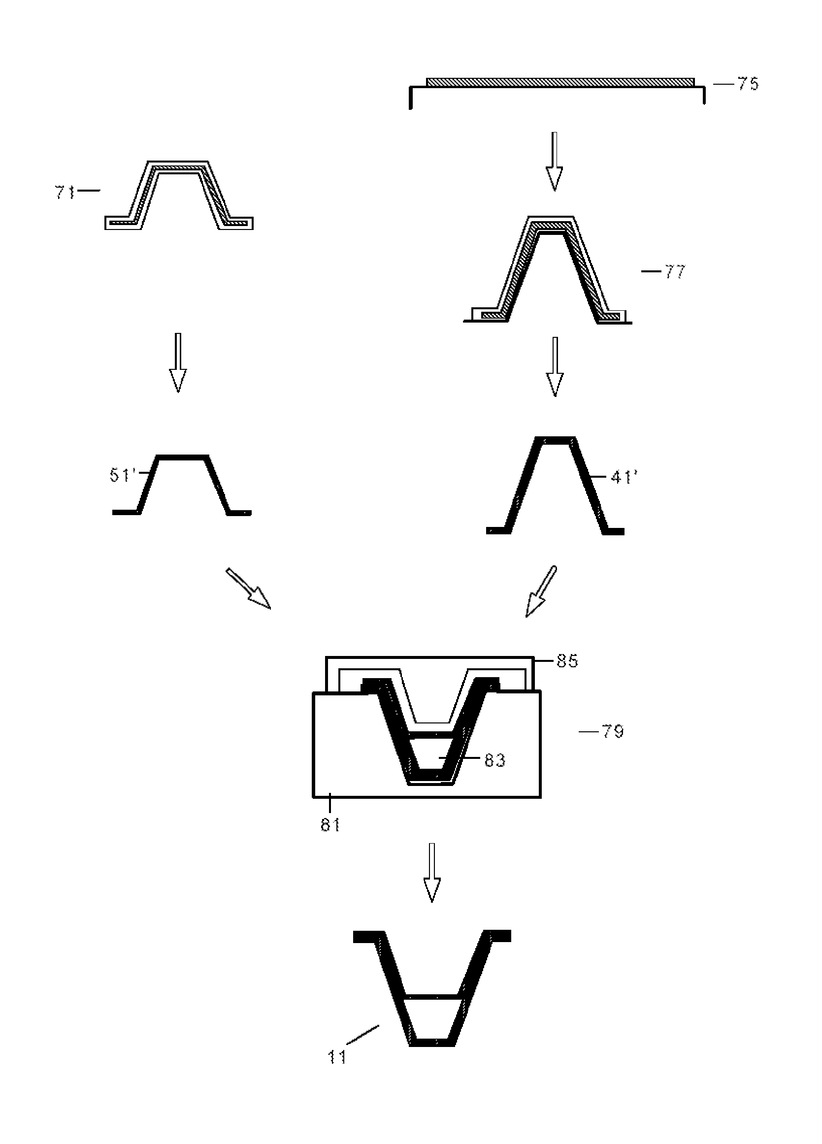
[0067]In a first stage 71, a preform 51′ of the internal element 51 would be manufactured and would be cured using an RTM (Resin Transfer Moulding) process (it is also feasible to do it with pre-impregnated material using a suitable tool). It is well known that this process uses a closed, pressuriz...

third embodiment

[0072]In a third embodiment variant of a procedure, according to the invention, to manufacture a segment of a frame with the aforementioned internal element 51 and external element 41, their preforms 51′, 41′ would be manufactured separately and, after a process of hot forming and duly arranged in appropriate tools, they would be co-cured together in a curing cycle in autoclave.


PUM

PropertyMeasurementUnit
thicknessaaaaaaaaaa
lengthaaaaaaaaaa
strength-to-weight ratioaaaaaaaaaa

Abstract

Aircraft fuselage frame (9) in composite material with stabilized web whose omega-shaped cross section (11) in at least a first segment (31) is formed by one head (23), two webs (25, 25′), two feet (27, 27′) with a stiffening element (29) between the two webs (25, 25′). The invention also refers to a manufacturing procedure for the first segment (31) comprising steps to: a) provide an external element (41) with an omega-shaped cross section formed by one head (43), two webs (45, 45′) and two feet (47, 47′), and an internal element (51) with omega-shaped section formed by one head (53), two webs (55, 55′) and two feet (57, 57′), with their respective webs (45, 55; 45′, 45′) and feet (47, 57; 47′, 57′) oriented in parallel; b) join the internal element (51) to the external element (41).

Description

FIELD OF THE INVENTION[0001]This invention refers to aircraft fuselage frames made of composite material, and more specifically to frames with stabilized webs.BACKGROUND OF THE INVENTION[0002]Load frames, in addition to shaping and stiffening the fuselage of an aircraft, are the structural elements in charge of withstanding and transferring the loads coming from other structural elements of the aircraft, e.g. the wings or the stabilizers.[0003]Traditionally, load frames have been made of metallic material and with different sections, the most usual ones being C-, I- and J-sections which, through machining processes, form a ribbed framework that stabilizes the web of the frame.[0004]In today's aeronautical industry, the strength-to-weight ratio is an element of utmost importance; therefore, there is a demand for frames manufactured or optimised with composite materials, primarily with carbon fibre, instead of metallic frames.[0005]In the case of load frames, it is difficult to compet...

Claims


Application Information

Patent Timeline
Patent Type & Authority Applications(United States)
IPC IPC(8): B64C1/06B29C45/02
CPCB29C70/446B29C70/46B29C70/48B29D99/0003B29L2031/3082B64C1/061Y10T428/24488Y02T50/433Y10T428/24661Y10T428/24628Y10T428/24182Y10T428/24174B64C2001/0072Y02T50/40
Inventor AREVALO RODR GUEZ, ELENA
Owner AIRBUS OPERATIONS SL
Why Eureka
Try Eureka