
Method for Constructing a Gray-Box Model of a System Using Subspace System Identification

a subspace system and gray box technology, applied in the field of system modeling, can solve the problems of inability to obtain in reasonable time, inability to understand the model, and inability to always find information, so as to reduce the dependence of system identification tasks, reduce complexity, and reduce the effect of compromising performan

Inactive Publication Date: 2011-06-30
MITSUBISHI ELECTRIC RES LAB INC
View PDF4 Cites 17 Cited by
  • Summary
  • Abstract
  • Description
  • Claims
  • Application Information

AI Technical Summary

Benefits of technology

[0019]The method has significant reduction in complexity without compromising performance. In addition, the method significantly reduces the dependence of the system identification task on iterative procedures.

Problems solved by technology

Such information is not always available, especially for old buildings.
White-box model tends to be overly complex, and possibly even impossible to obtain in reasonable time due to the complex nature of many systems.
However, the resulting model parameters have no physical meaning, and the model is difficult to understand.
However, the models operate as black-boxes during modeling.

Method used


Image

  • Method for Constructing a Gray-Box Model of a System Using Subspace System Identification
  • Method for Constructing a Gray-Box Model of a System Using Subspace System Identification
  • Method for Constructing a Gray-Box Model of a System Using Subspace System Identification

Examples


Embodiment Construction

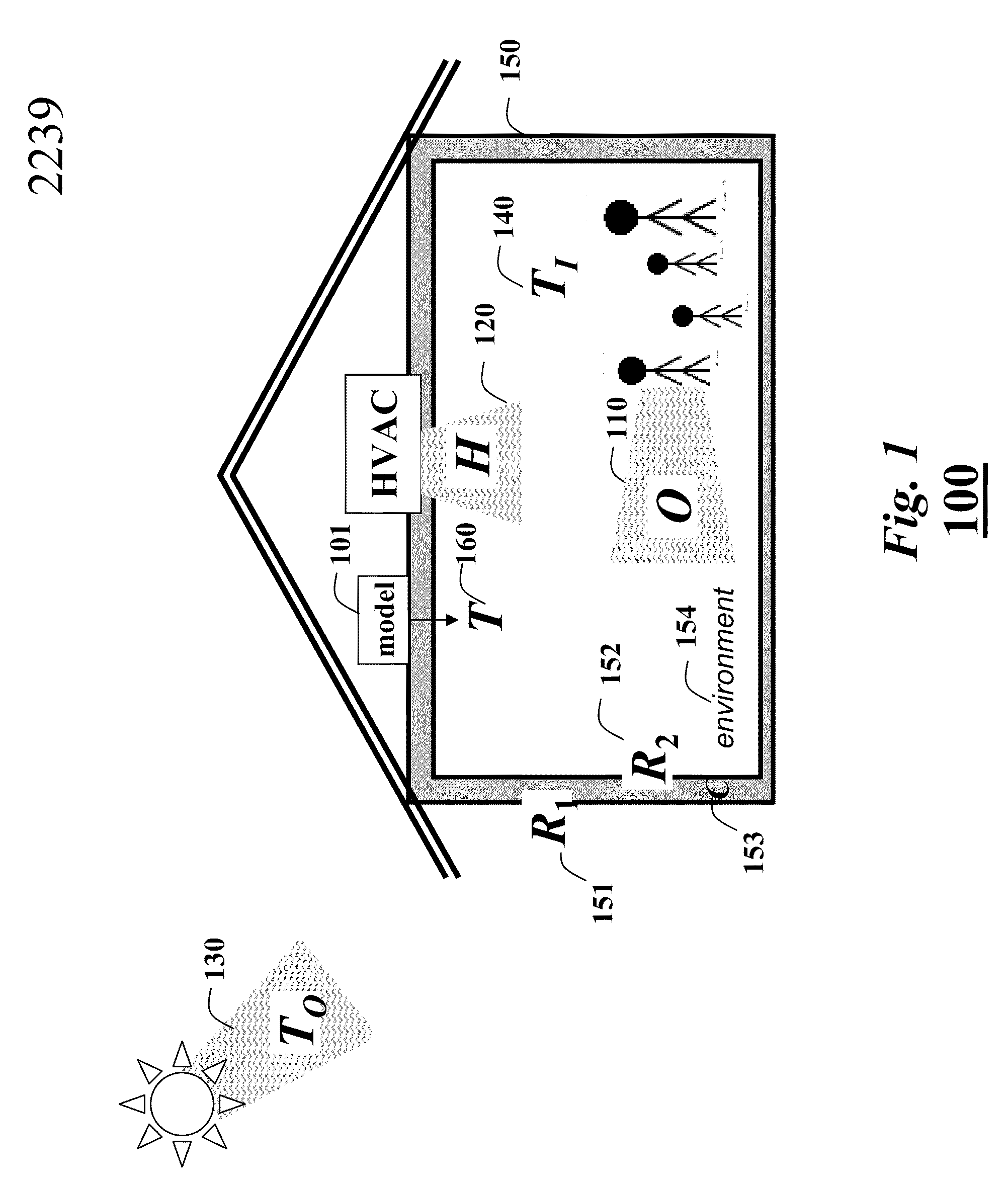
[0023]FIG. 1 shows a system 100 to be modeled according to embodiments of our invention. In an example application, the system is a building. We desired to model 101 heat transfer in the building.

[0024]The sources of heat for the inside of the building include the environment 154 (appliances, equipment, etc), occupant heat (O) 110, heating, ventilation and air conditioning (HVAC) (H) 120, solar radiation and outside environment heat (TO) 130. Occupancy statistics (location, density, and time) can also be provided. The temperature inside the building is TI 140.

[0025]System Constraints

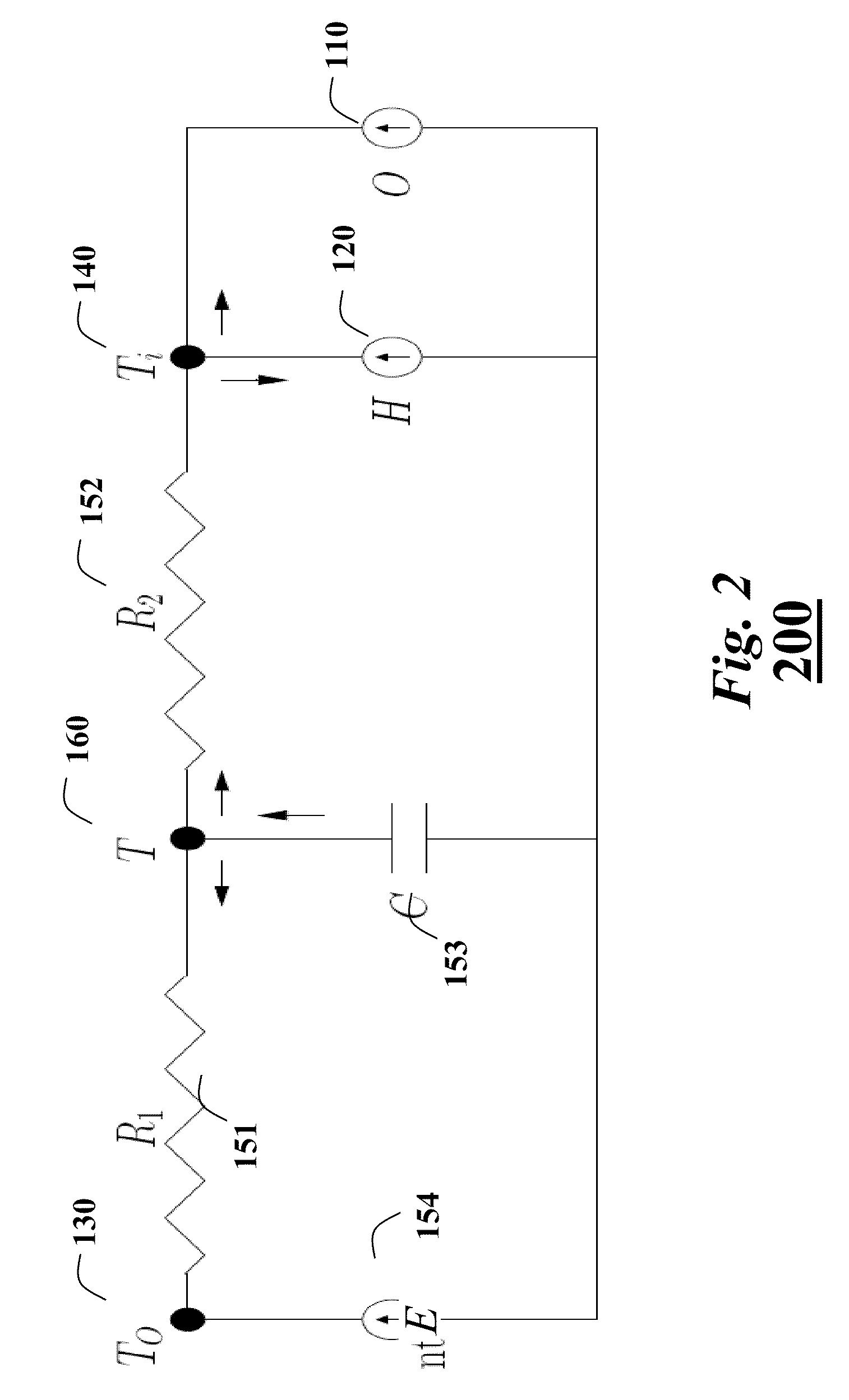
[0026]A resistance R1 151 models thermal transfer between an outside surface of a wall 150 and the outside environment, and a resistance R2 152 models the transfer between the inside surface of the wall and inside environment. The capacitance C 153 corresponds to the thermal mass of the wall.

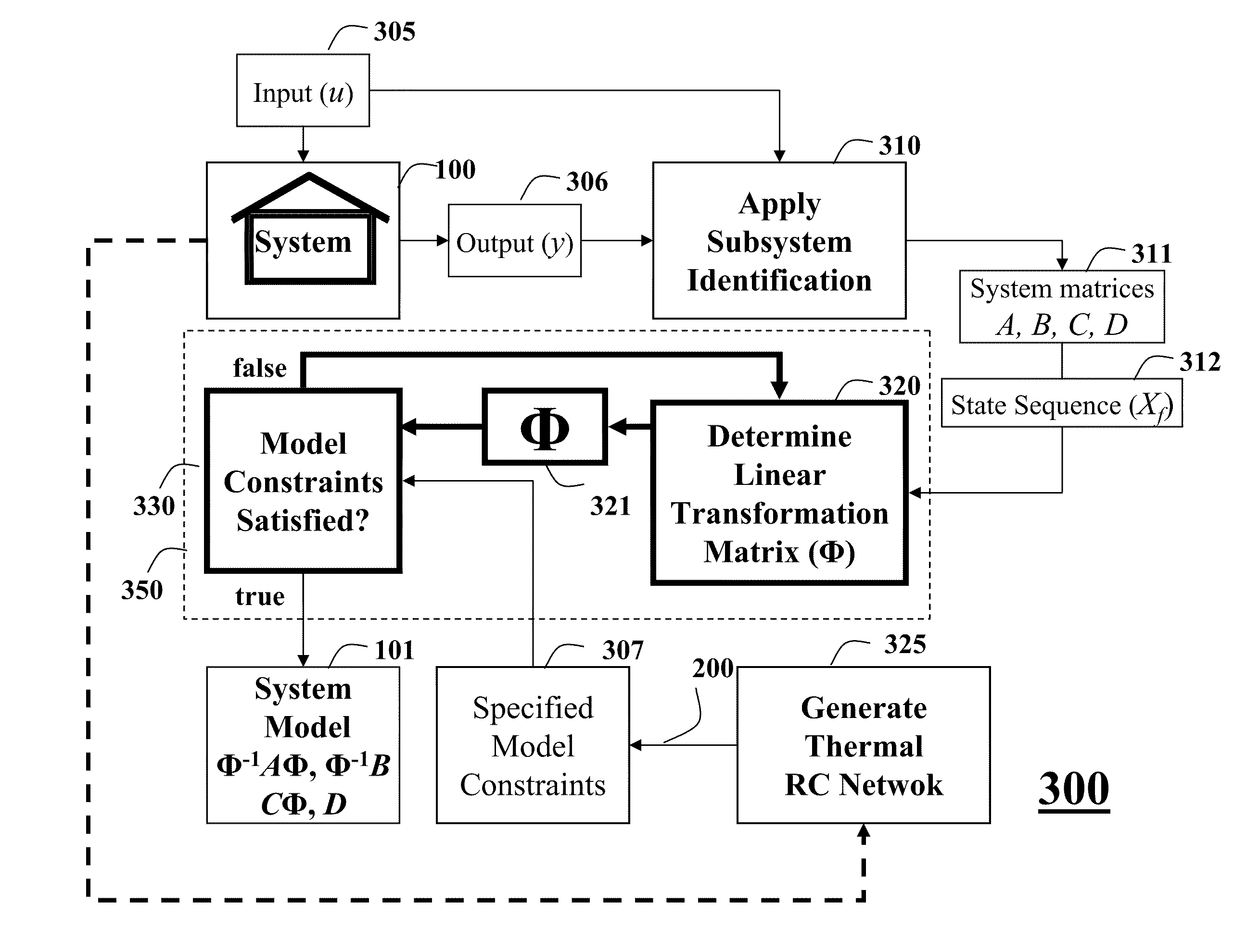
[0027]As shown in FIG. 3, the embodiments of the invention provide a method 300 for constructing the thermal model...


PUM


Abstract

A gray-box model of a system is constructed by specifying constraints for the system and applying subspace system identification to inputs and outputs of the system to determine system matrices and system state sequences for the system. A transformation matrix that satisfy the constraints from the system matrices and the system state sequences is determined, wherein the transformation matrix defines parameters of the gray-box model.

Description

FIELD OF THE INVENTION[0001]This invention relates generally to modeling systems, and more particularly to modeling heat transfer in buildings using gray-box models and subspace box system identification.BACKGROUND OF THE INVENTIONSystem Models[0002]A dynamical system model describes an operation of a system in either the time or frequency domain. The system of particular interest to the invention is a building, with occupants and environmental control subsystems. It is desired to model and predict heat transfer in buildings.[0003]White-Box Models[0004]A white-box model is based on fundamental known physical characteristics of the system. If the system is a building, then the white-box model requires detailed information about the building, such as thermal dynamics, geometry, thermal transfer coefficients, environmental control subsystems, and occupancy patterns. Such information is not always available, especially for old buildings. White-box model tends to be overly complex, and p...

Claims


Application Information

Patent Timeline
Patent Type & Authority Applications(United States)
IPC IPC(8): G06G7/56G06F17/10
CPCG05B17/02
Inventor JAIN, ANKURNIKOVSKI, DANIEL
Owner MITSUBISHI ELECTRIC RES LAB INC
Learn More