
I2c/spi control interface circuitry, integrated circuit structure, and bus structure thereof

a technology of control interface and integrated circuit, applied in the direction of electric digital data processing, instruments, etc., can solve the problems of system stability and data transmission quality degradation, and achieve the effect of enhancing stability and compatibility

Inactive Publication Date: 2011-06-30
ALCOR MICRO CORP
View PDF15 Cites 14 Cited by
  • Summary
  • Abstract
  • Description
  • Claims
  • Application Information

AI Technical Summary

Benefits of technology

[0013]The present invention provides an I2C / SPI control interface circuitry, an integrated circuit structure, and a bus structure thereof to enhance stability and compatibility between an I2C control module and an SPI control module and to ensure quality signal transmission.
[0014]The present invention provides an I2C / SPI control interface circuitry, an integrated circuit structure, and a bus structure thereof, which integrate the I2C control module and the SPI control module, so as to reduce the quantity of system output ports and thereby cut costs incurred in fabricating and packaging chips.
[0015]The present invention provides an I2C / SPI control interface circuitry, an integrated circuit structure, and a bus structure thereof, which achieve, with a special means of connection, the effective integration of an I2C serial communication bus and an SPI bus and the prevention of interference between signals.
[0020]1. Using an internal port electrical connection structure for effectively preventing interference between the I2C control module and the SPI control module in signal transmission;
[0021]2. Integrating the I2C control module and the SPI control module to thereby reduce the quantity of system output ports and cut costs incurred in fabricating and packaging chips; and
[0022]3. Using a special means of connection for enhancing stability and compatibility of the I2C / SPI control interface circuitry structure efficiently to thereby ensure quality signal transmission.

Problems solved by technology

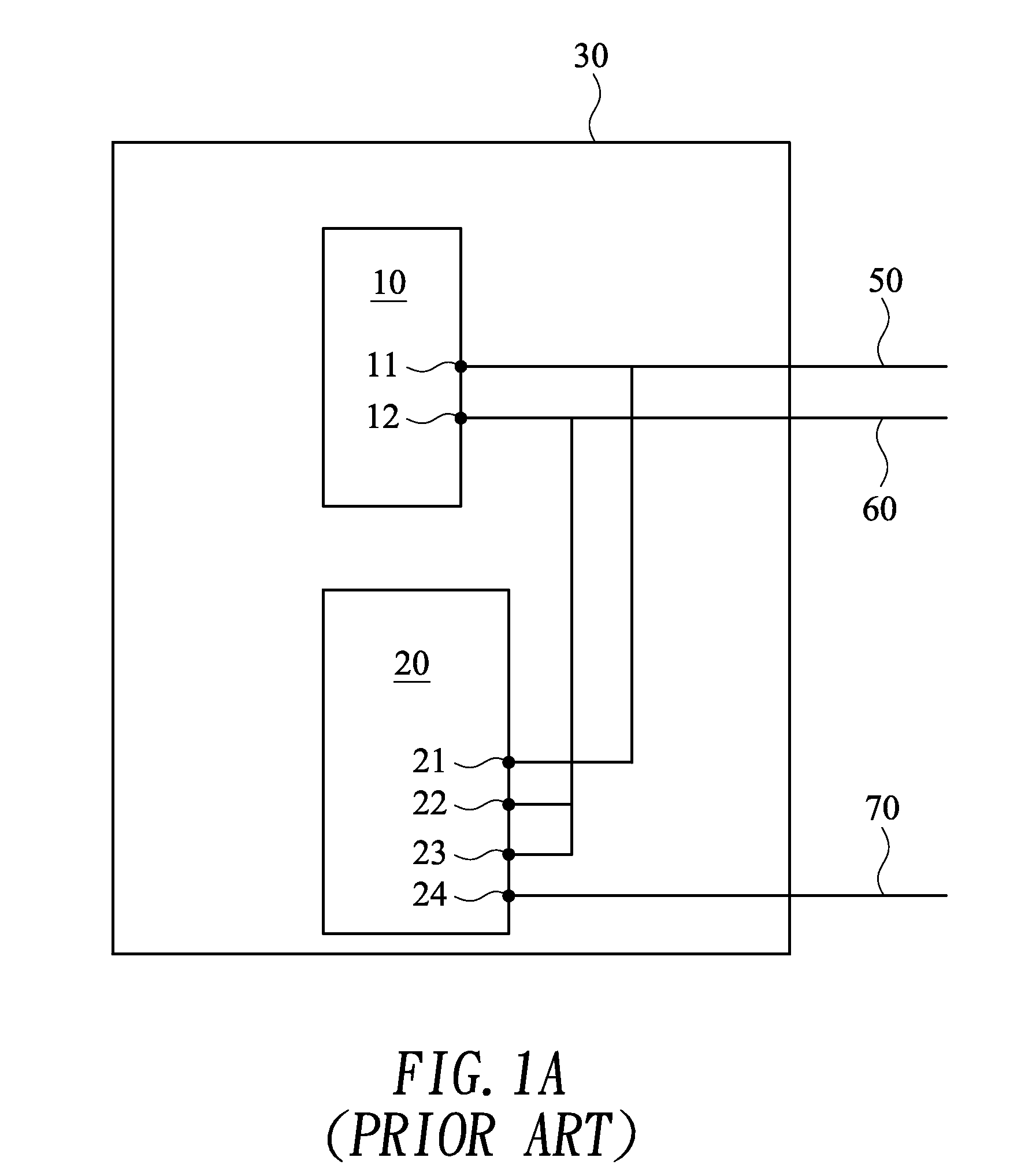
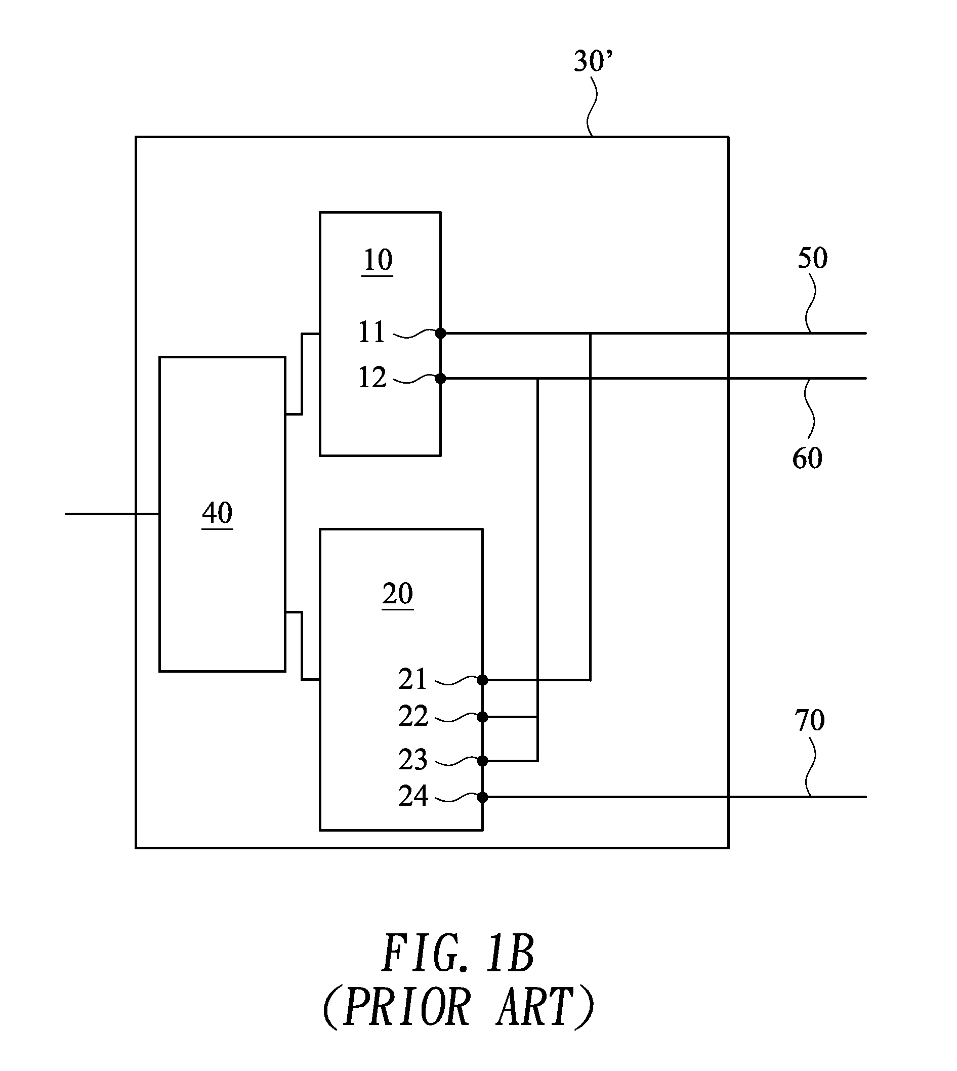
However, in practice, the two bus systems have different specifications and thus are incompatible.
As a result, there is signal interference between the I2C control module 10 and the SPI control module 20 to the detriment of system stability and the quality of data transmission.

Method used


Image

  • I2c/spi control interface circuitry, integrated circuit structure, and bus structure thereof
  • I2c/spi control interface circuitry, integrated circuit structure, and bus structure thereof
  • I2c/spi control interface circuitry, integrated circuit structure, and bus structure thereof

Examples


Embodiment Construction

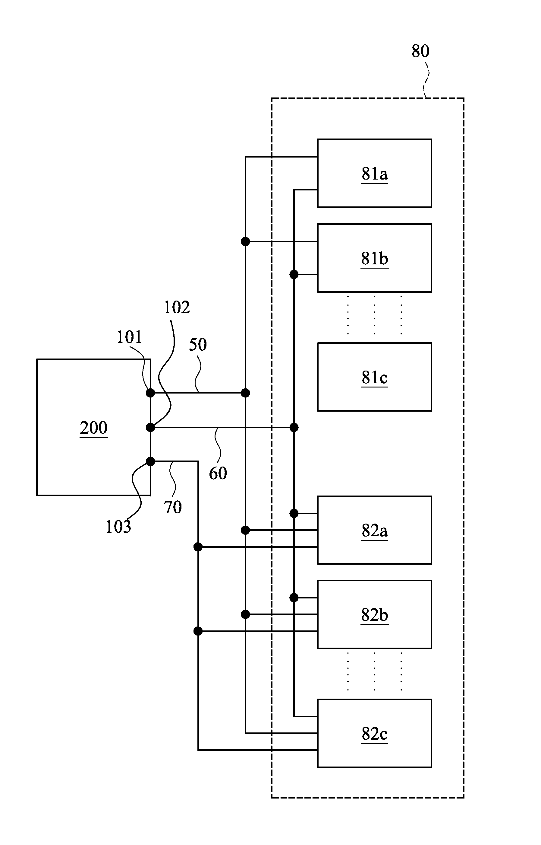
[0037]Referring to FIG. 4A, in this embodiment, an I2C / SPI control interface circuitry structure 100 includes an I2C control module 10 and an SPI control module 20.

[0038]The I2C control module 10 at least comprises an I2C clock port 11 and an I2C data port 12. The SPI control module 20 at least comprises an SPI clock port 21, an SPI data input port 22, an SPI data output port 23, and an SPI chip enable port 24.

[0039]The I2C clock port 11 and the SPI chip enable port 24 are electrically connected to form an I2C clock / SPI chip enable input / output end 101 for connection with a first transmission line 50. The I2C data port 12 is electrically connected with the SPI data input port 22 and the SPI data output port 23 so as to form an I2C / SPI data input / output end 102 for connection with a second transmission line 60. The SPI clock port 21 independently forms an SPI clock output end 103 for connection with a third transmission line 70.

[0040]Referring to FIG. 4B, an I2C / SPI control interface...


PUM


Abstract

An I2C / SPI control interface circuitry, an integrated circuit structure, and a bus structure thereof are provided. The I2C / SPI control interface circuitry includes an I2C control module and a SPI control module. The I2C control module has an I2C clock port and an I2C data port, and the SPI control module has a SPI clock port, a SPI data input port, a SPI data output port, and a SPI chip enable port. The I2C clock port is electrically connected with the SPI chip enable port to become an I2C clock / SPI chip enable input / output end. The I2C data port is electrically connected with the SPI data input port and the SPI data output port to become an I2C / SPI data input / output end. The SPI clock port is the SPI clock output end. The I2C and SPI control module are alternative to be enabled to avoid signal interference and lower the cost of the package and the manufacture of the integrated circuit.

Description

BACKGROUND OF THE INVENTION[0001]1. Technical Field[0002]The present invention relates to I2C / SPI control interface circuitries, integrated circuit structures, and bus structures thereof, and more particularly, to an I2C / SPI control interface circuitry, an integrated circuit structure, and a bus structure thereof advantageously configured to prevent signal interference and lower manufacture as well as packaging costs.[0003]2. Description of Related Art[0004]An I2C (inter-integrated circuit) serial communication bus and an SPI (serial peripheral interface) bus are master-slave bus systems in wide use and are configured to control various peripheral devices. However, in practice, the two bus systems have different specifications and thus are incompatible. Hence, it is imperative to render the two bus systems compatible to ensure quality transmission.[0005]FIG. 1A is a schematic view of a conventional I2C / SPI control interface circuitry structure 30. FIG. 1B is a schematic view of a co...

Claims


Application Information

Patent Timeline
IPC IPC(8): G06F13/40
CPCG06F13/38G06F13/4022G06F13/4068G06F2213/0016
Inventor CHANG, CHI-TUNGFAN, HSIU MINGTSAI, CHUAN-CHING
Owner ALCOR MICRO CORP
Learn More