Waste Heat Steam Generator

a waste heat steam generator and generator technology, applied in the direction of machines/engines, steam separation arrangements, lighting and heating apparatus, etc., can solve the problems of significant extra costs and restrictions on the geometrical parameters of the waste heat steam generator, and achieve the effects of preventing the operation of flow turbulence dampers, simple construction, and preventing too great mechanical stress

Active Publication Date: 2011-07-07
SIEMENS ENERGY GLOBAL GMBH & CO KG
View PDF2 Cites 18 Cited by
  • Summary
  • Abstract
  • Description
  • Claims
  • Application Information

AI Technical Summary

Benefits of technology

[0026]In order to arrange the components necessary for breaking these slugs to function correctly in the tubes upstream from the water separation elements, the direction of vibration in the wave movements entering the flow turbulence dampers should be known and predictable. In particular possible swirling movements of the inflowing water-steam mixture should be suppressed, since these can prevent the operation of the flow turbulence dampers. To this end the flow turbulence dampers advantageously contain a number of guide profiles aligned in the main flow direction of the flow medium on the inner tube wall. A possible swirling movement of the water-steam mixture is stopped by the guide profile and the water-steam mixture is introduced in such a geometrical position into the flow turbulence damper that the latter can expediently fulfill its function.
[0027]To make an especially simple construction of the flow turbulence dampers possible the flow turbulence dampers can be inserted directly during the production of the tubes. To this end the flow turbulence dampe...

Problems solved by technology

The space problems which can be involved in accommodating this type of large number of water separation elements mean that such a design, as a result of the high...

Method used


Image

  • Waste Heat Steam Generator
  • Waste Heat Steam Generator
  • Waste Heat Steam Generator

Examples


Embodiment Construction

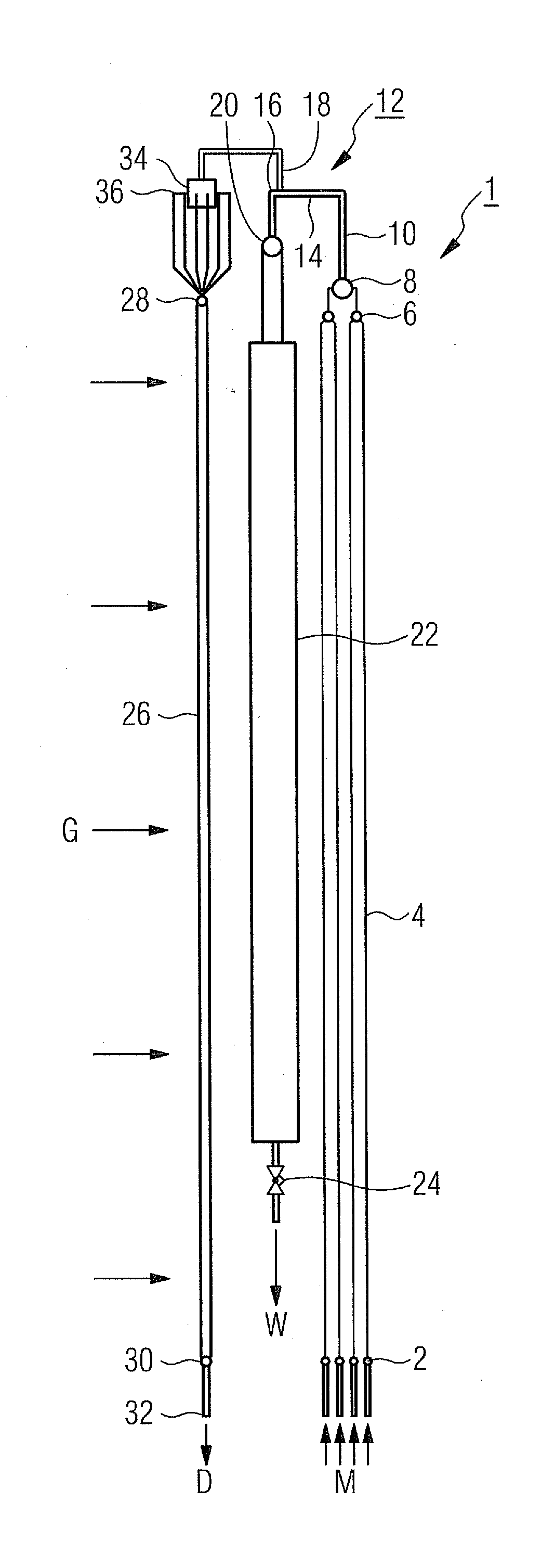
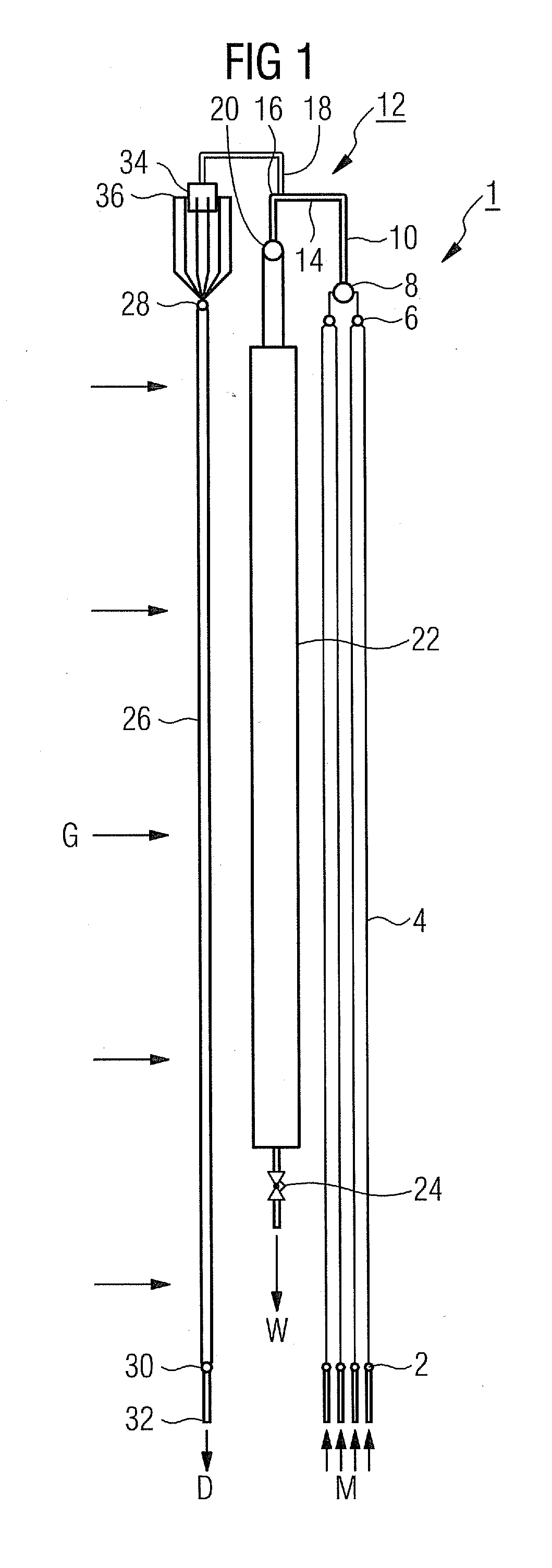
[0036]FIG. 1 shows a schematic diagram of waste heat steam generator 1 with horizontal flue gas path. The flow medium M is injected into the tube system from an upstream feed pump not shown in the figure. Initially it flows in this case into a number of evaporator inlet collectors 2 which handle the distribution of the flow medium M to four evaporator heating surfaces with evaporator tubes 4 in which the flow medium is then evaporated. If necessary further evaporator heating surfaces can also be connected upstream or the heating surfaces can be arranged in the hot gas duct in different geometrical embodiments.

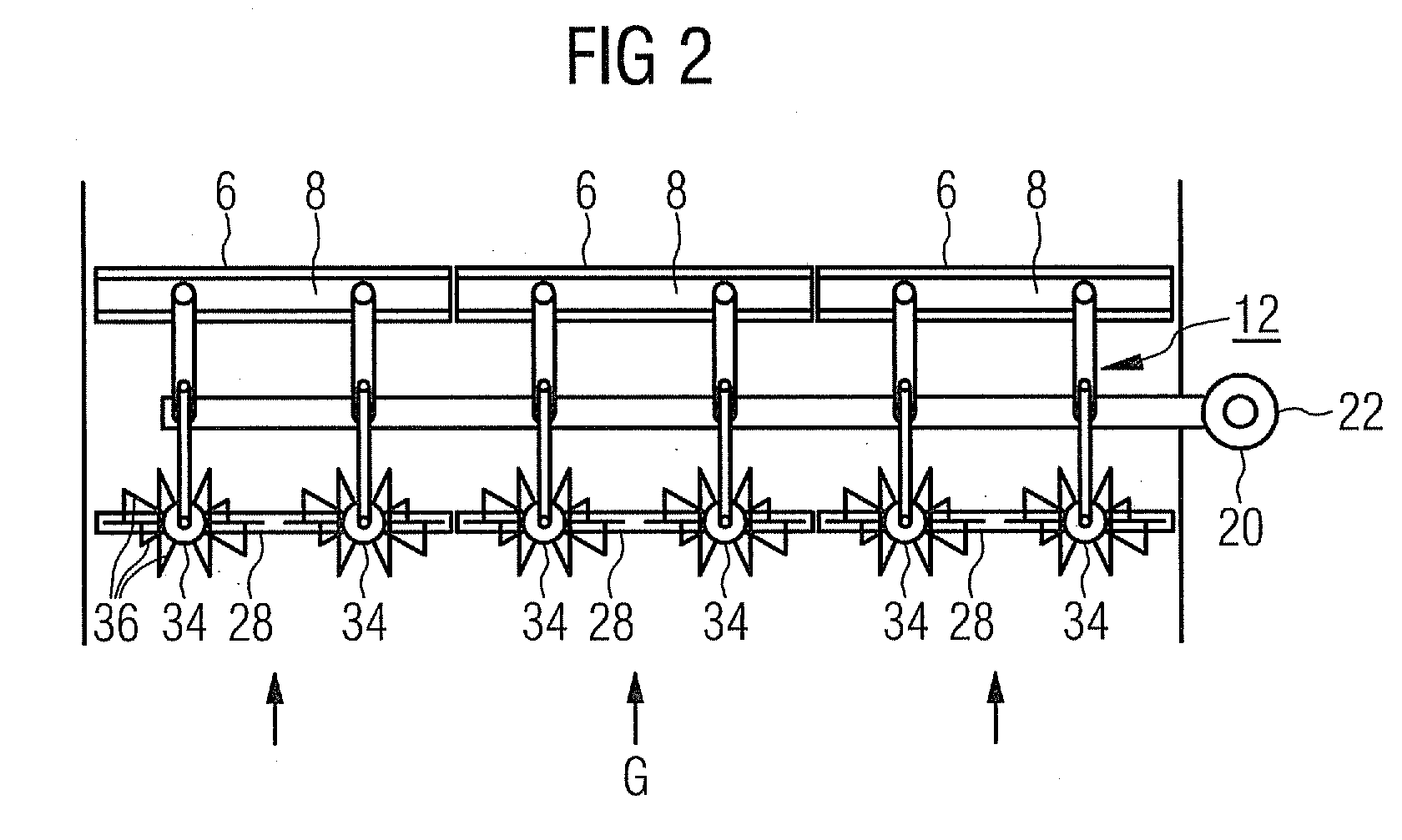
[0037]A number of evaporator tubes 4 in each case open out into a common transitional tube section 10 over a first evaporator exit collector 6 and a second exit collector 8, downstream of which is connected the T-piece water separator element 12. The T-piece water separator element comprises an inflow tube section 14 which, when seen in its longitudinal direction, extends into ...


PUM


Abstract

A waste heat steam generator including evaporator tubes is provided. The evaporator tubes are connected in parallel on the flow medium side, a plurality of overheating tubes are mounted downstream of the evaporator tubes using a water separation system. The water separation system includes water separation elements, each water separation element being respectively mounted downstream of the plurality of evaporator tubes and/or upstream of a plurality of overheating tubes. Each water separating element includes an inlet pipe which is respectively connected upstream to the evaporator tubes, the inlet pipe extending into a water evacuation pipe when seen in the longitudinal direction. A plurality of outflow pipes branch off in the transitional area, the pipes being connected to an inlet collector of the overheating tubes which are respectively connected downstream. A distribution element is arranged on the steam side between the respective water separating element and the inlet collector.

Description

CROSS REFERENCE TO RELATED APPLICATIONS[0001]This application is the US National Stage of International Application No. PCT / EP2009 / 061521, filed Sep. 7, 2009 and claims the benefit thereof. The International Application claims the benefits of European Patent Office application No. 08015864.5 EP filed Sep. 9, 2008. All of the applications are incorporated by reference herein in their entirety.FIELD OF INVENTION[0002]The invention relates to a waste heat steam generator having a plurality of evaporator tubes which are connected in parallel on the flow medium side, downstream of which is mounted a plurality of superheating tubes, with the water separation system comprising a number of water separation elements, downstream of each of which is connected a number of evaporator tubes and / or upstream of which is connected a number of superheater tubes, with each of the water separation elements comprising an inflow tube section connected to a respective upstream evaporator tubes which, when...

Claims


Application Information

Patent Timeline
IPC IPC(8): F22B1/00
CPCF22B15/00F22B37/26F22B21/00
Inventor BRUCKNER, JANFRANKE, JOACHIMSCHMIDT, HOLGERTHOMAS, FRANK
Owner SIEMENS ENERGY GLOBAL GMBH & CO KG
Why Eureka
Try Eureka