Super-ring resonator based devices

Active Publication Date: 2011-07-07
MORTON PHOTONICS INC
View PDF5 Cites 12 Cited by
  • Summary
  • Abstract
  • Description
  • Claims
  • Application Information

AI Technical Summary

Benefits of technology

[0022]The tunability is achieved either by thermo-optical effect, by quantum confined Stark effect, by carrier injection, by Franz-Keldysh effect, by Pockels effect (depending on material) or by MEMS. The resonant angular frequencies ω1 and

Problems solved by technology

One of the key issues with using thermal tuning of a device, is that there are usually multiple time constants involved in the tuning, i.e. although the goal is to achieve fast (e.g. microsecond) tuning times, which may be achieved by the device structure itself, when it is done thermally there are typically much longer time constants also involved, due to the thermal mass of the whole device, the submount, the heatsink it is placed on, the cooling circuit that keeps the temperature constant etc.
These much slower time constants, which can be as long as many seconds, cause changes in the device output on these longer time

Method used


Image

  • Super-ring resonator based devices
  • Super-ring resonator based devices
  • Super-ring resonator based devices

Examples


Embodiment Construction

[0041]Optical delay lines typically use near infrared (NIR) light, however the disclosure is not limited to this spectral range. The term “optical” in the present disclosure comprises visible, near infrared, infrared, far infrared and the near and far ultra-violet spectra.

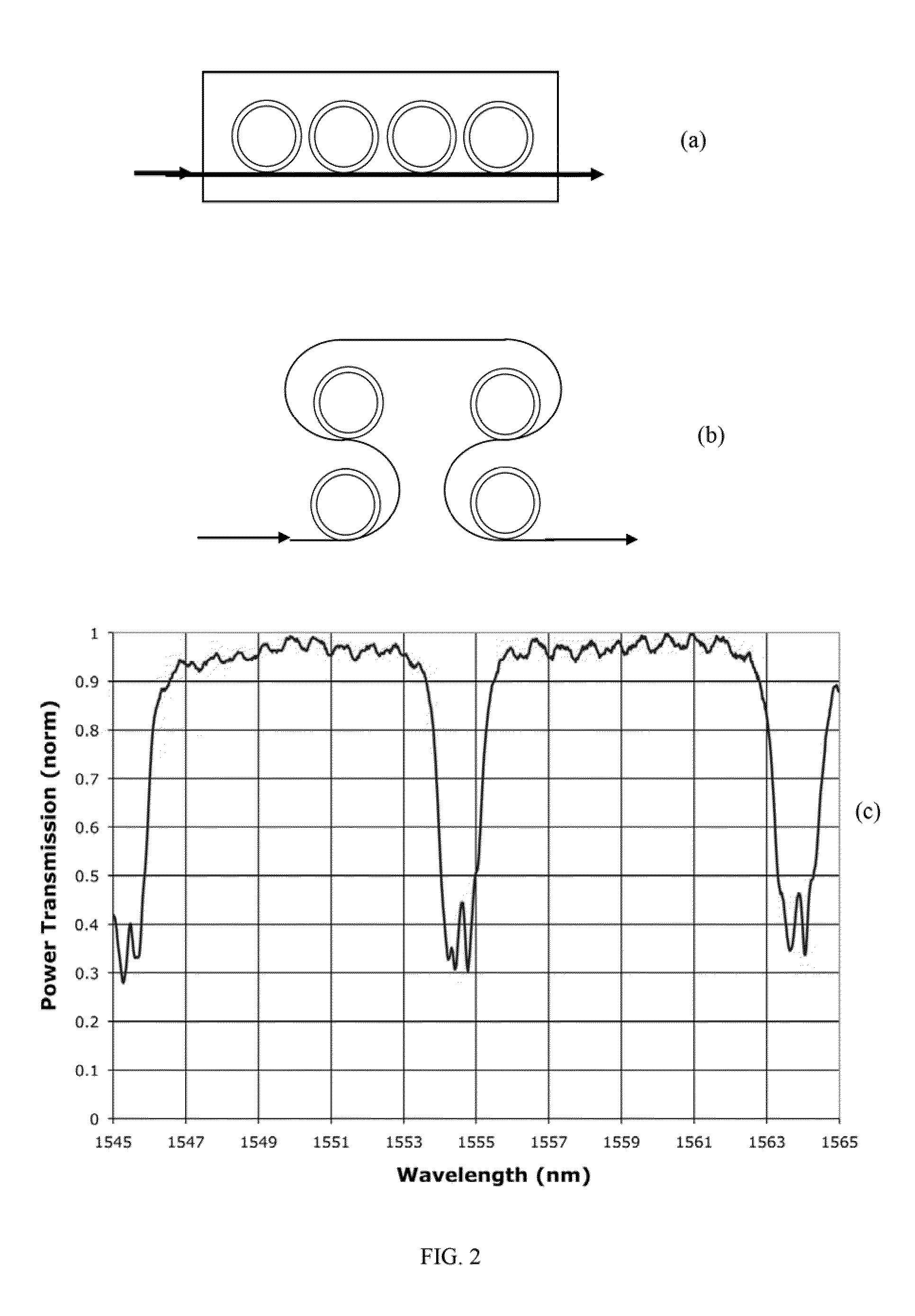
[0042]The prior art shows that the phase shift in the SCISSOR delay line. (shown in FIG. 2 (a)) with N rings each having a round-trip time τ can be written as

tan(ΦN)=κ2sin(ω-ωr)τ(1+ρ2)cos(ω-ωr)τ-2ρ(1)

[0043]where the resonant frequency is ωr=2 mπτ−1 and τ is around trip time, and the coupling between the resonator and waveguide is κ=√{square root over (1−ρ2)} The group delay can then be written as

Td(ω)=∂Φ(ω)∂ω=Nτ1+ρ1-ρ-nτ3(1+ρ)ρ(1-ρ)3(ω-ωr)2+112Nτ5(1+ρ)ρ(1+10ρ+ρ2)(1-ρ)5(ω-ωr)4+…==Td0-Nβ3(ω-ωr)2+Nβ5(ω-ωr)4+…(2)

[0044]where we have introduced higher order group delay dispersion (GDD) terms β3 and β5. It is these terms that are responsible for the different delay experienced by different frequency components of the sign...


PUM


Abstract

This invention provides an optical device comprising a large group of non-uniform resonators operating cumulatively as a ‘super-ring’ to provide a controllable group delay with large bandwidth. The super-ring tuning is performed by a single control. The device may include two super-rings, each includes a large number of resonators with a resonant frequencies centered around ω1 and ω2 respectively. The invention provides multiple ways to improve the delay duration, bandwidth and the tuning speed, and overcomes the issue of non-uniformity of resonance frequency for devices incorporating multiple optical resonators.

Description

CROSS-REFERENCE TO RELATED APPLICATIONS[0001]The application is a continuation-in-art of U.S. patent application Ser. No. 12 / 897,219 filed Oct. 4, 2010, which is a continuation-in-part of U.S. patent application Ser. No. 12 / 205,368 filed Sep. 5, 2008.STATEMENT REGARDING FEDERAL SPONSORED RESEARCH AND DEVELOPMENT[0002]This invention was made with U.S. Government support under Contract W31P4Q-09-C0298 with DARPA MTO SBIR Project, and the U.S. Government has certain rights in the invention.FIELD OF INVENTION[0003]This invention relates to an active array antenna system for use in wireless communications. More particularly it addresses tunable delays to control phased array antennas.BACKGROUND OF THE INVENTION[0004]A phased array is a group of radio frequency antennas in which the relative phases of the respective signals feeding the antennas are varied in such a way that the effective radiation pattern of the array is reinforced in a desired direction and suppressed in undesired direct...

Claims


Application Information

Patent Timeline
IPC IPC(8): G02B26/06
CPCG02F1/011G02F2201/20H01Q3/2682H01Q3/26H01Q3/2676G02F2203/15G02B6/29395G02B6/2861G02B6/29343G02B6/29398G02B6/4286G02F1/0147G02F2203/055
Inventor MORTON, PAUL A.KHURGIN, JACOB
Owner MORTON PHOTONICS INC
Why Eureka
Try Eureka