Switch cabinet connection and combination apparatus and method of manufacturing the same
a technology of combination apparatus and switch cabinet, which is applied in the direction of switchgear with horizontal withdrawal, electric apparatus casing/cabinet/drawer, high-tension/heavy-dress switch, etc., can solve the problems of gas leakage, sf6 gas harming operators and the ambient environment, and potential threat to the “greenhouse effect” effect, and achieves low volume , the effect of low cos
- Summary
- Abstract
- Description
- Claims
- Application Information
AI Technical Summary
Benefits of technology
Problems solved by technology
Method used
Image
Examples
first embodiment
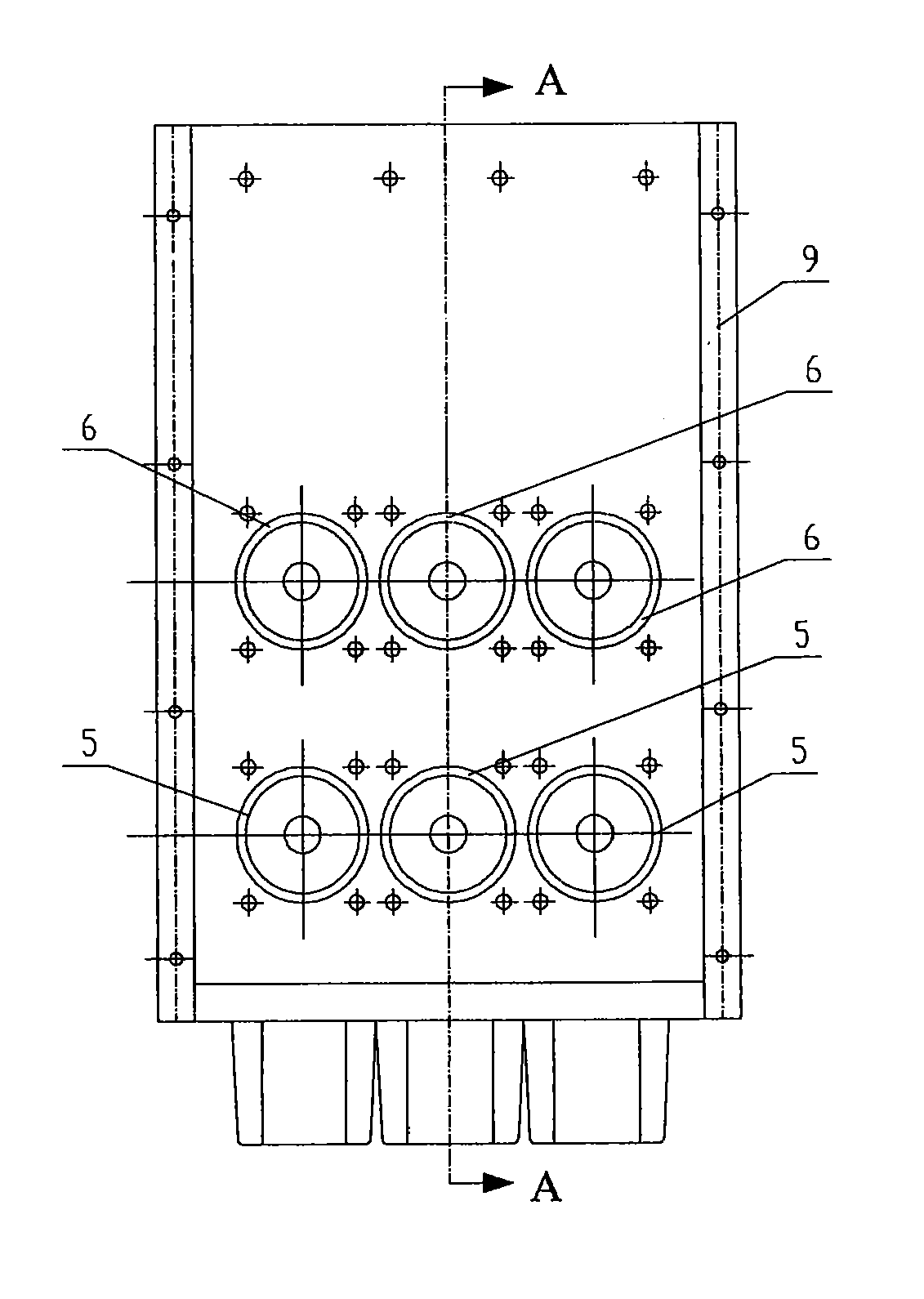
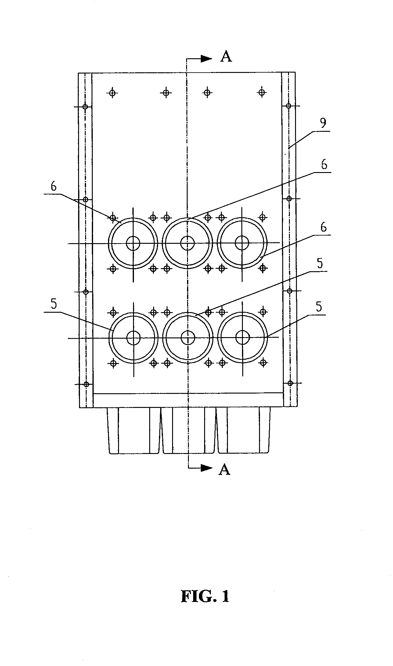
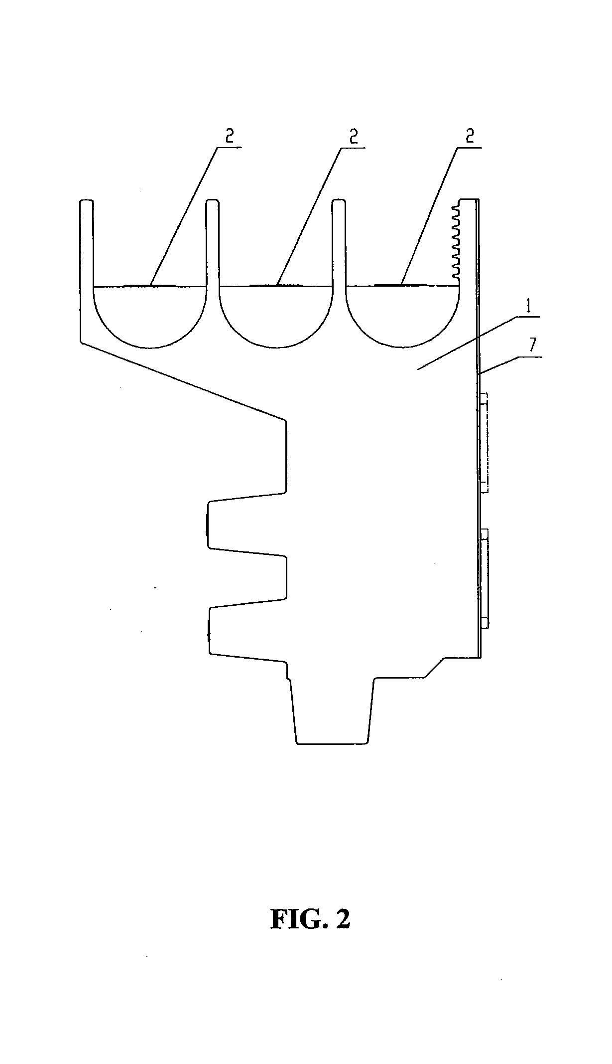
[0059]FIG. 1 is a main view of the connection and combination apparatus in the invention, through which 3 lower contact boxes 5, 3 upper contact boxes 6 and the mounting plate 9 which are exposed out of the casing 7 can be seen from this view. The left view thereof is shown in FIG. 2, through which the upper line-in / line-out terminals 2, the solid state insulating layer 1 and the casing 7 can be seen from this view. FIG. 3 is a rear view thereof including the solid state insulating layer 1 and lower line-in / line-out terminals 4. FIG. 4 is a top view including upper line-in / line-out terminals 2 and the mounting plate 9.
[0060]As shown in FIG. 5, in the cutaway view along the A-A direction of FIG. 5, the upper line-in / line-out terminals 2 of the three phases of A, B, C are connected via the conductor 3 to the upper contact box 6 connected to the casing 7, and thus are upper line-in / line-out terminals; the lower line-in / line-out terminals 4 of the three phases of A, B, C are connected v...
second embodiment
[0062]In the second embodiment as shown in FIGS. 6A and 6B, the connection and combination apparatus of the invention are divided into three independent functional units A, B, and C according to different functions of the three phases of A, B and C, as shown in FIG. 6A. The upper line-in / line-out terminals 2 in each functional unit are connected to the upper contact boxes 6 via the conductor 3 as the upper line-in / line-out terminals; the lower line-in / line-out terminals 4 are connected to the lower contact boxes 5 via the conductor 3 as the lower line-in / line-out terminals; then, the solid insulating material 1 is added for pouring once as individual independent functional units for embedded poles. The three independent functional units A, B, and C, together with the mounting plate 9, are fixed at the nuts 8 via bolts 15, as shown in FIG. 6B.
third embodiment
[0063]In the third embodiment as shown in FIGS. 7A and 7B, the connection and combination apparatus of the invention is divided into two functional units D, E, as shown in FIG. 7A. D represents that the upper line-in / line-out terminals 2 are connected to the upper contact box 6 via the conductor 3 as the upper line-in / line-out terminals, and then the solid insulating material 1 is added for pouring molding once as an upper independent functional unit. E represents that the lower line-in / line-out terminals 4 are connected to the lower contact boxes 5 via the conductor 3 as the lower line-in / line-out terminals, and then the solid insulating material 1 is added for pouring molding once as a lower independent functional unit. The two independent functional units D, E, together with the mounting plate 9 are fixed at the nuts 8 via the bolts 15, as shown in FIG. 7B.
PUM
| Property | Measurement | Unit |
|---|---|---|
| distance | aaaaa | aaaaa |
| rated current | aaaaa | aaaaa |
| voltage | aaaaa | aaaaa |
Abstract
Description
Claims
Application Information
 - R&D
- Intellectual Property
- Life Sciences
- Materials
- Tech Scout
- Unparalleled Data Quality
- Higher Quality Content
- 60% Fewer Hallucinations
Browse by: Latest US Patents, China's latest patents, Technical Efficacy Thesaurus, Application Domain, Technology Topic, Popular Technical Reports.
© 2025 PatSnap. All rights reserved.Legal|Privacy policy|Modern Slavery Act Transparency Statement|Sitemap|About US| Contact US: help@patsnap.com


