Receiver device, integrated circuit, receiving method, and receiving program

a multi-carrier, modulated signal technology, applied in the direction of frequency-division multiplex, pulse technique, amplitude demodulation, etc., can solve the problem of signal processing carried out using a different sub-carrier position, the sub-carrier position is different, and the data errors become larger. problem, to achieve the effect of stable reception

Active Publication Date: 2011-07-07
PANASONIC CORP
View PDF7 Cites 42 Cited by
  • Summary
  • Abstract
  • Description
  • Claims
  • Application Information

AI Technical Summary

Benefits of technology

[0060]According to the above-described receiving device, when receiving multi-carrier modulated signals transmitted using one among a plurality of location patterns which determine the plurality of sub-carrier positions in which the predetermined signals are arranged, even if the location pattern actually in use is unclear, the wideband carrier frequency error can be detected and carrier frequency discrepancies can be corrected, thus making possible stable reception despite degraded reception environments.BRIEF DESCRIPTION OF FIGURES
[0061]FIG. 1 is a configuration diagram of the receiver pertaining to Embodiment 1.
[0062]FIG. 2 is a configuration diagram of the demodulator from FIG. 1.
[0063]FIG. 3 is a configuration diagram of the P1 demodulator from FIG. 2.
[0064]FIG. 4 is a configuration diagram of the P1 WAFC from FIG. 3.
[0065]FIG. 5 is a configuration diagram of the correlator from FIG. 4.

Problems solved by technology

The greater the narrowband carrier frequency discrepancies, the greater the data errors become.
Also, the presence of wideband carrier frequency discrepancies causes discrepancies in sub-carrier positions.
As such, signal processing is carried out using a different sub-carrier and demodulation cannot be accomplished.
This presents difficulties for steady reception.

Method used


Image

  • Receiver device, integrated circuit, receiving method, and receiving program
  • Receiver device, integrated circuit, receiving method, and receiving program
  • Receiver device, integrated circuit, receiving method, and receiving program

Examples


embodiment 1

[0144]The following describes a receiver 1 pertaining to Embodiment 1 of the present invention, with reference to the figures. It should be noted that for Embodiment 1 as well as for successive Embodiments, examples of receivers are described as operable to receive second-generation European terrestrial digital broadcasts according to the DVB-T2 scheme. The signals received by the receivers are OFDM signals based on the DVB-T2 transmission format.

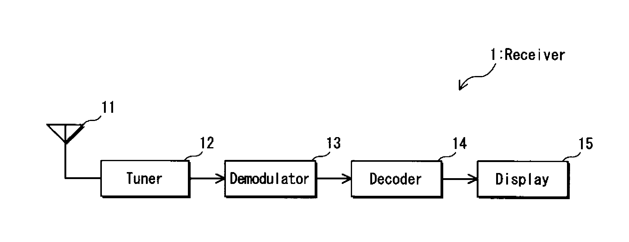
[0145]FIG. 1 is a configuration diagram of the receiver 1 pertaining to Embodiment 1 of the present invention. The receiver 1 comprises an antenna 11, a tuner 12, a demodulator 13, a decoder 14, and a display 15.

[0146]The antenna 11 receives broadcast waves provided by a broadcasting station (not diagrammed) and outputs the broadcast waves so received to the tuner 12. The tuner 12 selects a desired reception channel signal out of a plurality of broadcast waves input from the antenna 11, converts the selected reception signals from the RF ba...

embodiment 2

[0233]Embodiment 2 of the present invention is described below with reference to the figures. It should be noted that those structural elements of Embodiment 2 which are substantially equivalent to structural elements of Embodiment 1 use identical reference numbers and are here omitted as Embodiment 1 may be referred to for explanations thereof.

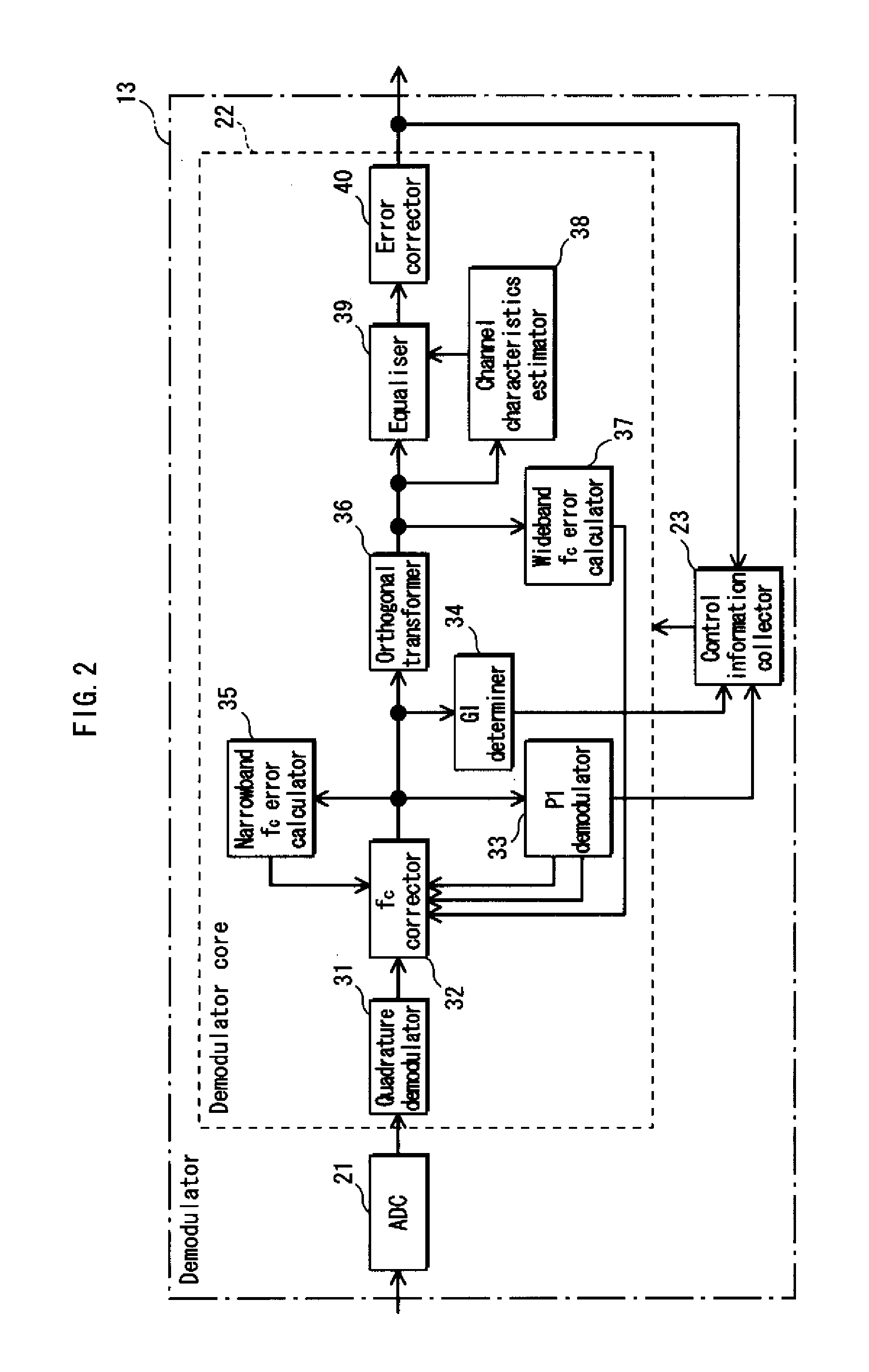
[0234]The wideband fc error calculator 37 of Embodiment 1 has a number of correlators 2021 through 20216 that is equal to the number of combinations pilot pattern and carrier mode, and correlation is performed in parallel on the CP signal location pattern of all such combinations.

[0235]In contrast, the wideband fc error calculator 37A of Embodiment 2 uses a single correlator 202A to perform correlation on the CP signal location pattern of all combinations of pilot pattern and carrier mode in serial order.

[0236]The wideband fc error calculator 37A of Embodiment 2 is described below with reference to FIG. 11. As shown, the wideband fc error cal...

embodiment 3

[0240]Embodiment 3 of the present invention is described below with reference to the figures. It should be noted that those structural elements of Embodiment 3 which are substantially equivalent to structural elements of Embodiment 1 use identical reference numbers and are here omitted as Embodiment 1 may be referred to for explanations thereof.

[0241]The wideband fc error calculator 37B of Embodiment 3 and the wideband fc error calculator 37C of the later-described Embodiment 4 have a smoothing function for the signals output from the differential detector 201 in addition to the functions of the wideband fc error calculator 37 from Embodiment 1.

[0242]The wideband fc error calculator 37B of Embodiment 3 is described below with reference to FIG. 12. As shown, the wideband fc error calculator 37B comprises the structure of the wideband fc error calculator 37 (see FIG. 6) as well as a squarer 291 and an inter-symbol filter 292.

[0243]The differential detection signals output from the dif...


PUM


Abstract

A wideband carrier frequency error calculator that, for each of a plurality of location patterns, calculates a cumulative value through a predetermined process performed on signals output by an orthogonal transformer for a plurality of sub-carrier positions determined according to a given location pattern while simultaneously shifting the signals output therefrom by one sub-carrier unit along the carrier direction and that also calculates wideband carrier frequency error according to carrier direction discrepancies calculated as maximum values within the cumulative value, and a carrier frequency error corrector that applies corrections to carrier frequency discrepancies according to the wideband carrier frequency error so calculated.

Description

TECHNICAL FIELD[0001]The present invention relates to technology for receiving multi-carrier modulated signals in which a plurality of sub-carriers have been multiplexed.BACKGROUND ART[0002]Presently, Orthogonal Frequency Division Multiplexing (OFDM) is a broadcasting scheme widely used for various types of digital transmission, notably including terrestrial digital broadcasting and the IEEE 802.11a standards. The OFDM scheme makes highly efficient use of frequencies by frequency multiplexing a plurality of narrowband digitally-modulated signals using mutually-orthogonal sub-carriers.[0003]Additionally, in the OFDM scheme, the length of one symbol comprises the length of a useful symbol as well as the length of a guard interval. As such, a portion of the useful symbol-length signal is reproduced at length the guard interval to produce intra-symbol periodicity. Thus, the influence of inter-symbol interference caused by multi-pass interference can be reduced given that such a scheme o...

Claims


Application Information

Patent Timeline
Patent Type & Authority Applications(United States)
IPC IPC(8): H04L27/00H04L27/06H03H7/30
CPCH04L27/2659H04L27/2666H04L27/2676H04L27/2675H04L27/2672
Inventor MATSUMURA, YOSHINOBU
Owner PANASONIC CORP
Why Eureka
Try Eureka