
Method of operating a convertible fan engine

a technology of convertible fans and engine, which is applied in the direction of machines/engines, marine propulsion, vessel construction, etc., can solve the problems of large increase in part-power installed specific fuel consumption levels, limited capacity of current turbofan engines to supply this type of mission adaptive performance, and lack of operational flexibility, so as to reduce the flow

Inactive Publication Date: 2011-07-14
GENERAL ELECTRIC CO
View PDF57 Cites 23 Cited by
  • Summary
  • Abstract
  • Description
  • Claims
  • Application Information

AI Technical Summary

Benefits of technology

[0008]The above-mentioned need or needs may be met by exemplary embodiments disclosed herein which provide a method of operating a gas turbine engine having the steps of directing a flow of air to a front fan stage at a selected fan flow rate, fan speed and front fan stage pressure ratio corresponding to a selected first operating power level, pressurizing a portion of the flow from the front fan stage in a aft fan rotor to a first tip pressure ratio to generate a first overall fan pressure ratio, selecting a second operating power level that is lower than the first operating power level and reducing the flow in the aft fan rotor and pressurizing to a second tip pressure ratio to generate a second overall pressure ratio that is substantially lower than the first overall fan pressure ratio while the flow rate in the front fan stage is held substantially constant.

Problems solved by technology

Current turbofan engines are limited in their capabilities to supply this type of mission adaptive performance, in great part due to the fundamental operating characteristics of their existing fan systems which have limited flexibility in efficiently reducing fan pressure ratio while maintaining high levels of fan flow.
This lack of operational flexibility limits the possibility of fully optimizing part power uninstalled specific fuel consumption levels.
Further, the limitations in the current fan systems severely restrict making major improvements in spillage and nozzle closure drag losses that cause large increases in part-power installed specific fuel consumption levels.
Future mixed mission morphing aircraft as well as more conventional mixed mission capable military systems that have a high value of take-off thrust / take-off gross weight, i.e., a thrust loading in the 0.8-1.2 category, present many challenges to the propulsion system.
They need efficient propulsion operation at diverse flight speeds, altitudes, and particularly at low power settings where conventional engines operate at inefficient off-design conditions both in terms of uninstalled performance and, to an even greater degree, fully installed performance that includes the impact of spillage drag losses associated with both subsonic and supersonic inlets.
In particular, the fan pressure ratio and related bypass ratio selection needed to obtain a reasonably sized engine capable of developing the thrusts needed for combat maneuvers and supersonic operation are non-optimum for efficient low power subsonic flight.
Basic uninstalled subsonic engine performance is compromised and fully installed performance suffers even more due to the inlet / engine flow mismatch that occurs at reduced power settings.
In the art, the core concepts used in convertible engines are quite complex, having multiple cores with complex ducting and valving needs.
Current conventionally bladed core in engines cannot maintain constant or near constant operating pressure ratios as core flow is reduced.
Current conventionally bladed fan rotors do not have the flexibility in efficiently reducing fan pressure ratio while maintaining high levels of fan flow.
This lack of operational flexibility limits the possibility of fully optimizing part power uninstalled specific fuel consumption levels.
This severely limits the potential Specific Fuel Consumption (SFC) advantage offered by known variable bypass convertible engine concepts.

Method used


Image

  • Method of operating a convertible fan engine
  • Method of operating a convertible fan engine
  • Method of operating a convertible fan engine

Examples


Embodiment Construction

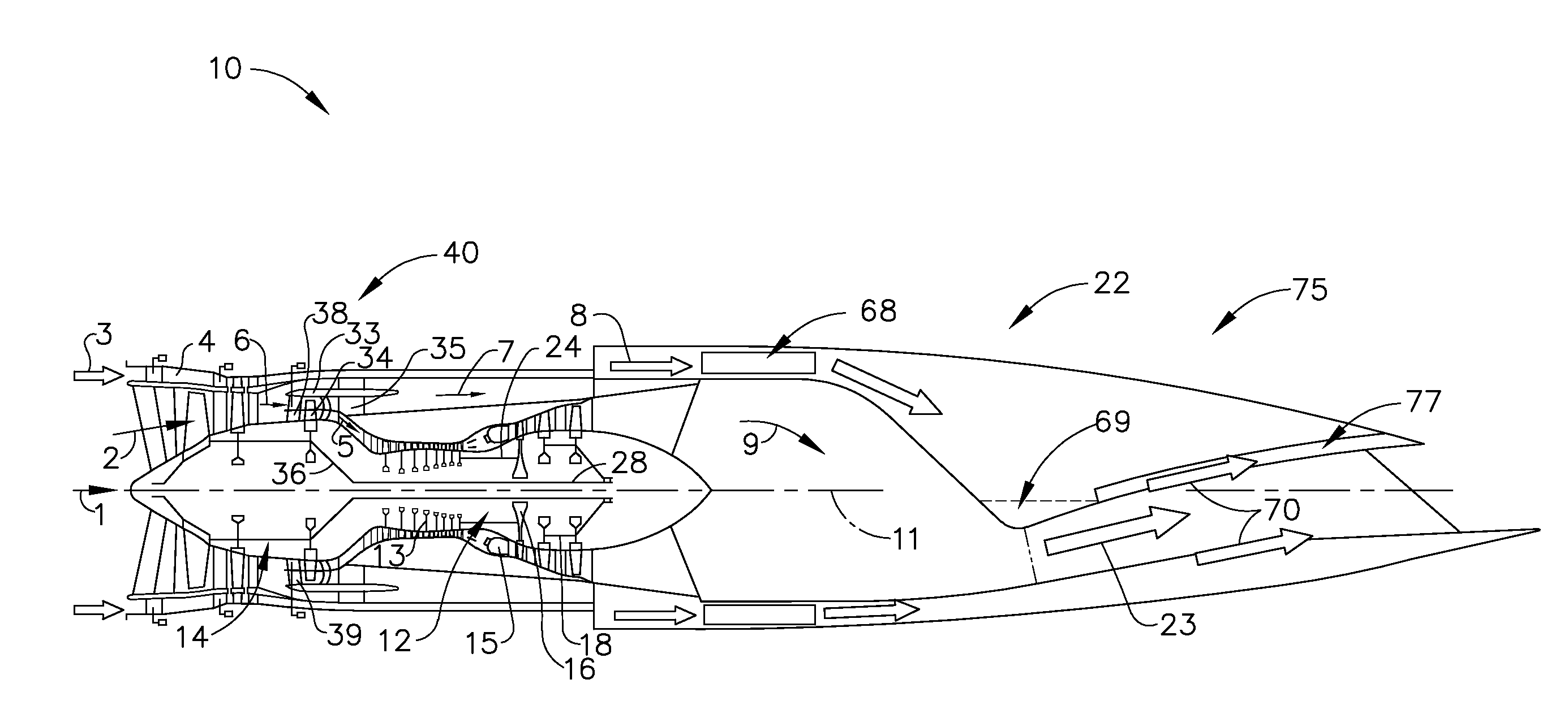
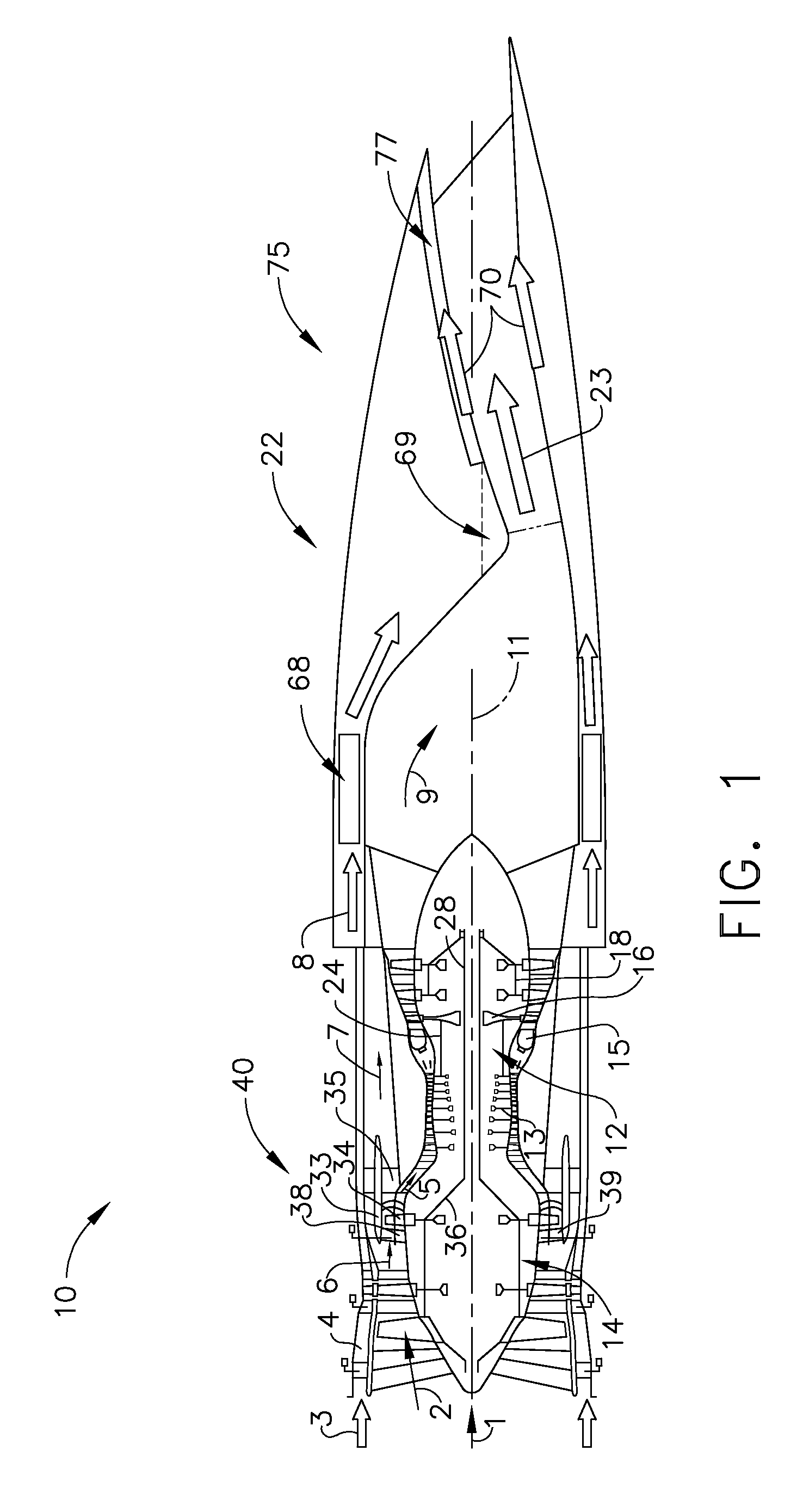
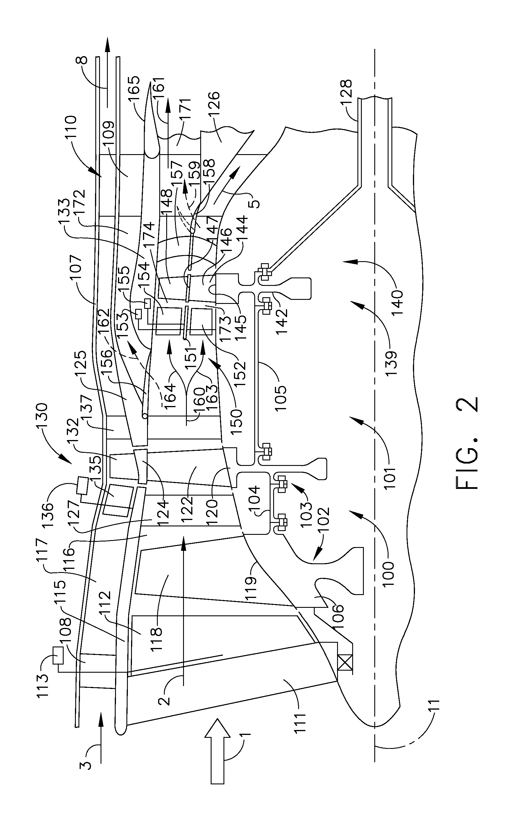
[0021]Referring to the drawings wherein identical reference numerals denote the same elements throughout the various views, FIG. 1 is a schematic cross-sectional view of an adaptive, versatile gas turbine engine 10 according to an exemplary embodiment of the present invention. The gas turbine engine 10 has a fan 14, a core 12 comprising a compressor 13 driven by a high-pressure turbine (HPT) 16 shaft 24. The fan 14 comprises a convertible fan system 40 having a longitudinal axis 11 and is driven by a low-pressure turbine (LPT) 18 shaft 28. The HPT 16 and LPT 18 are driven by the hot combustion gases from a combustor 15. In some applications, the engine 10 may optionally have an outer flow passage 4 that receives an outer flow stream 3 and an outer fan system as described subsequently herein. The inlet air flow stream 1 enters the front of the engine 10. The fan flow stream 2 is pressurized by the fan 14 and splits into one or more bypass flow streams 6 and a core flow stream 5. The ...


PUM


Abstract

A method of operating a gas turbine engine is disclosed having the steps of directing a flow of air to a front fan stage at a selected fan flow rate, fan speed and front fan stage pressure ratio corresponding to a selected first operating power level, pressurizing a portion of the flow from the front fan stage in a aft fan rotor to a first tip pressure ratio to generate a first overall fan pressure ratio, selecting a second operating power level that is lower than the first operating power level and reducing the flow in the aft fan rotor and pressurizing to a second tip pressure ratio to generate a second overall pressure ratio that is substantially lower than the first overall fan pressure ratio while the flow rate in the front fan stage is held substantially constant.

Description

CROSS-REFERENCE TO RELATED APPLICATIONS[0001]This application claims priority to U.S. Provisional Application Ser. No. 61 / 246,075, filed Sep. 25, 2009, and to U.S. Provisional Application Ser. No. 61 / 263,107, filed Nov. 20, 2009, which are herein incorporated by reference in their entirety.BACKGROUND OF THE INVENTION[0002]This invention relates generally to jet propulsion engines, and more specifically to versatile engines having convertible fan systems capable of operating under variable flow conditions and pressure ratios.[0003]Many current and most future aircraft need efficient installed propulsion system performance capabilities at diverse flight conditions and over widely varying power settings for a variety of missions. Current turbofan engines are limited in their capabilities to supply this type of mission adaptive performance, in great part due to the fundamental operating characteristics of their existing fan systems which have limited flexibility in efficiently reducing ...

Claims


Application Information

Patent Timeline
Patent Type & Authority Applications(United States)
IPC IPC(8): F02K3/075
CPCF01D17/162F02C7/042F02C9/18F05D2220/327F02K3/075F02K3/077F02C9/20
Inventor JOHNSON, JAMES EDWARDPOWELL, BRANDON FLOWERS
Owner GENERAL ELECTRIC CO
Learn More